User guide
 Monoceros: a Wave Function
Collapse plug-in for Grasshopper by Subdigital
Monoceros: a Wave Function
Collapse plug-in for Grasshopper by Subdigital
1. Authors
- Ján Pernecký: jan@sub.digital
- Ján Tóth: yanchi.toth@gmail.com, yanchith, GitHub
- Subdigital: sub.digital, GitHub
2. Tl;dr
Monoceros is a Grasshopper plug-in that fills the entire world with Modules, respecting the given Rules.
3. Table of contents
- 1. Authors
- 2. Tl;dr
- 3. Table of contents
- 4. Meet Monoceros
- 5. Wave Function Collapse
- 6. Development notes
- 7. Architecture of Monoceros Grasshopper plug-in
- 8. Data types
- 9. Monoceros WFC Solver
- 11. Examples
- 11.1. Bare minimum
- 11.2. Explicit Rules
- 11.3. Typed Rules
- 11.4. Indifferent Rules
- 11.5. Defining more Modules at once
- 11.6. Slots and Module Parts with non-uniforms dimensions
- 11.7. Modules and Envelope with individual base planes
- 11.8. Disallowing Rules
- 11.9. Modules with more Parts
- 11.10. Empty Module and allowing an Empty neighbor
- 11.11. Allowing Modules to be at the boundary of the Envelope
- 11.12. Constructing Slots
- 11.12.1. Definition: Slots from manually generated points
- 11.12.2. Definition: Slots from manually generated points from geometry
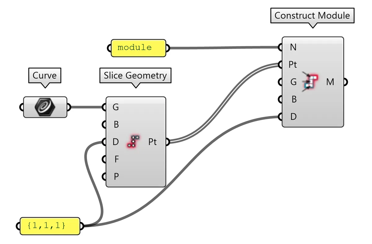
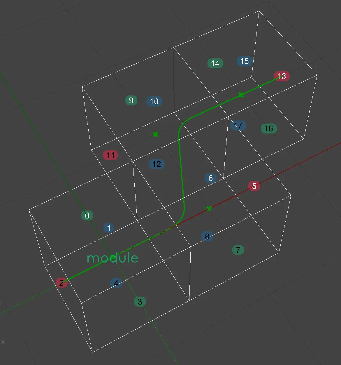
- 11.12.3. Definition: Slots from Slice Geometry: Points
- 11.12.4. Definition: Slots from Slice Geometry: Curves
- 11.12.5. Definition: Slots from Slice Geometry: Surfaces
- 11.12.6. Definition: Slots from Slice Geometry: Mesh and Brep volumes
- 11.12.7. Definition: Slots from Slice Geometry: Miscellaneous geometry
- 11.13. Allowing certain Modules in
certain
Slots
- 11.13.1. Definition: Allowing / Disallowing Modules in certain area
- 11.13.3. Definition: Allowing / Disallowing Modules based on attractor
- 11.13.4. Roulette approach to weighted probability
- 11.13.5. Definition: Roulette - Choosing a binary weighted option
- 11.13.6. Definition: Roulette - Choosing one weighted option from multiple choices
- 11.13.7. Definition: Roulette - Choosing more weighted options from multiple choices
- 11.13.8. Definition: Allowing Modules based on vertical gradient
- 11.13.9. Definition: Allowing Modules based on multiple attractor gradients
- 11.14. Fixing Modules in Envelope before running the Solver
- 11.15. Disallowing certain Modules from certain Slots
- 11.16. Enforcing specific modules at the boundary of the Envelope
- 11.17. Growing the boundary of the Envelope
- 11.18. Materializing results
- 11.19. Proto-results and custom materialization
- 11.20. Using the transform data to materialize the result
- 11.21. Random seed and attempts count
- 11.22. Visualizing Rules
- 11.23. Visualizing allowed Module couples
- 12. FAQ
- 12.1. What is a good exercise to start using Monoceros?
- 12.2. What does the error "World state is contradictory" mean?
- 12.3. Why the Solver cannot find any solution even after 1000 attempts?
- 12.4. What makes a good Module?
- 12.5. What makes a good Envelope?
- 12.6. Why does the Slice Geometry component give invalid results?
- 12.7. How to set a Rule for a Module distant two or more Slots?
- 12.8. Are block instances or groups supported by Monoceros?
- 13. Partners
- 14. MIT License
4. Meet Monoceros
Monoceros is a legendary animal living in the huge mountains in the interior of India. Monoceros has the body of a horse, the head of a stag, the feet of an elephant and the tail of a boar. from Unicorn Wiki
It is also a plug-in for Grasshopper, which is a visual programming platform for Rhinoceros 3D CAD software. Monoceros was developed at studio Subdigital by Ján Toth and Ján Pernecký. Monoceros is an implementation of the Wave Function Collapse (WFC) algorithm developed for game design by Maxim Gumin and extended and promoted by Oskar Stålberg with his game Townscaper.
Monoceros serves to fill the entire world with Modules, respecting the given Rules. The plug-in wraps WFC into a layer of abstraction, which makes WFC easily implemented in architectural or industrial design. It honors the principles of WFC and Grasshopper at the same time - offering a full control of the input and output data in a Grasshopper way and their processing with a pure WFC.
5. Wave Function Collapse
Before we delve deeper, let's shortly explain the WFC algorithm itself. Note that Monoceros extends some concepts over the vanilla WFC, but it is very helpful to understand the original version of the algorithm first. To that end, it might also be helpful to watch the excellent explanatory talk by Oskar Stålberg at EPC2018.
Wave Function Collapse (WFC) is a procedural generation algorithm that essentially attempts to satisfy constraints on a world (see CSP for more). Its name is inspired by quantum mechanics, but the similarity is just at the surface level - WFC runs completely deterministically.
In its simplest form the algorithm works on an orthogonal grid. We initially have:
-
A world defined by a mathematical graph, in our case represented as an orthogonal 3D grid.
-
A set of Rules describing what can occupy each tile on the grid depending on what its neighbors are.
The grid tiles are graph nodes, also called Slots in WFC (and in Monoceros). Graph edges are implicitly derived from Slot adjacency: two Slots are connected by an edge, if they are adjacent to each other on the grid. Every Slot contains a list of Modules that are allowed to reside in it. Conceptually, Modules could have any meaning that we assign to them, some usual meanings being that the Slots populated by them contain geometry, images, navigation meshes, or other high-level descriptions of a space.
The algorithm is defined as follows:
-
Initialize the world to a fully non-deterministic state, where every Slot allows every defined Module.
-
Repeat following steps until every Slot allows exactly one Module (a valid, deterministic result), or any Slot allows zero Modules (a contradiction):
-
Observation (Slot choice): Pick a Slot at random from the set of Slots with the smallest Module count that are still in non-deterministic state (allow more than one Module),
-
Observation (Module choice): Randomly pick a Module from the set of still available Modules for the chosen Slot and remove all other Modules from this Slot, making it deterministic (allowing exactly one Module),
-
Constraint Propagation: Remove Modules from neighboring Slots based on the Rules. Repeat recursively in depth-first order for each Slot modified this way.
-
-
If WFC generated a contradictory result, start over again with a different random state.
WFC does not necessarily always find a solution. If (and how quickly) a valid solution is computed very much depends on the set of provided Rules. There are sets of Rules for which WFC always converges in just a single attempt regardless of the random state, but also sets of Rules for which the simulation always results in a contradictory world state, and also everything in between. Rule design is a challenging part of working with Wave Function Collapse.
7. Architecture of Monoceros Grasshopper plug-in
The core of Monoceros is a Wave Function Collapse (WFC) solver. WFC is an algorithm that fills the entire discrete envelope with Modules with no remaining empty Slot. In case of Monoceros, the envelope is a collection of rectangular cuboid Slots, each with 6 neighbors in orthogonal directions, not taking diagonal neighbors into account. In the original WFC algorithm, the Modules are exactly the size of a single Slot. WFC then picks which Module should be placed into which Slot, leaving no Slot non-deterministic (with more than one Module allowed to be placed into the Slot) or empty / contradictory (no Module allowed to be placed into the Slot). Usually, there are less Modules (Module types) than Slots, which means each Module can be placed into Slots more times or not at all.
The Monoceros implementation of WFC internally works like this too, on the outside it presents the Modules as a continuous coherent compact collection of such cuboid cages (Module Parts), each fitting into one Slot.
Like Grasshopper itself, also Monoceros revolves around data and serves for its immutable processing. Immutability means, that no existing data is being changed but rather transformed and returned as a new instance of the data. In most cases it is even possible to construct the data with valid values right away with no need to re-define already existing data.
There are three main data types: Slots, Modules and Rules.
Slot and Rule both reference to Module, its Part or its Connector. This reference is done only through user defined strings (for Modules and their Parts) or integer indices (for Module Connectors). This is an intention, so that the data sets (Modules, Rules or Slots) can be replaced or shared across more Monoceros setups.
| Construct | Solve | Post process | ||
|---|---|---|---|---|
| Modules | -> | |||
| Rules | -> | WFC Solver | -> | Materialize |
| Slots | -> | |||
| Aggregate | ||||
| Preview |
Most of the Monoceros plug-in components serve for constructing, analyzing and processing data. The components try not to bring redundancy, therefore it does not do anything, that could be easily done with vanilla Grasshopper components. The three new Monoceros data types are seamlessly integrated into Grasshopper and cast from and to all relevant existing data types. All Monoceros components are compatible with the existing Grasshopper data types and ready to be used with existing Grasshopper components.
8. Data types
8.1. Slot
Slot is a cuboid (orthogonal box) that represents the basic unit of the Monoceros rigid discrete grid. The Slots do not overlap and their position coordinates are defined in discrete numerical steps. The Slots are stacked next to each other, preferably forming a coherent continuous blob or more separate blobs that should become filled with Modules. Such blob will be called an Envelope.
8.1.1. States
Slot is a container that allows placement of certain Modules or their Parts. The Slot can be in several states:
- Allows Nothing is a contradictory (invalid) state, when there is no Module or its Part that can be placed inside the Slot. If the collection of Slots forming the Envelope of the solution contains one or more such Slots, the solution cannot be found and therefore such setup is invalid.
- Allows one Module (or deterministic state) is the desired state of a Slot. It is the responsibility of the WFC Solver to bring a non-deterministic Slot into a deterministic state. Such Slot can be Materialized - a Module can be placed into the Slot.
- Allows more Modules (or non-deterministic state) is usually an initial or intermediate state of a Slot, when it is not yet clear, which Module or its Part should be placed inside the Slot, but a list of allowed Modules is present. It is the responsibility of the WFC Solver to bring a non-deterministic Slot into a deterministic state. A non-deterministic Slot cannot be Materialized yet but it is possible to evaluate its level of entropy - a number of currently allowed Modules or their Parts stating how far from the deterministic state the Slot is.
- Allows all Modules is a shortcut for a fully non-deterministic state, when any Module or its Part is allowed to be placed inside the Slot. In practice this state exists only for cases, when Slots are being defined before or independently from Modules and therefore it is not possible to list Modules that should be allowed by the Slot.
The collection of Slots forming an Envelope is considered Canonical if the adjacent Slots allow placement of such Modules or their Parts, that are allowed to be neighbors by the Rules. Canonical Envelope does not have to be also deterministic. For non-deterministic Slots to form a Canonical Envelope, each allowed Module or its Part in one Slot must be allowed to be a neighbor of each allowed Module or its Part in its adjacent Slot in the given direction by the Rule set.
The Monoceros implementation of the WFC algorithm can automatically clean a Non-Canonical Envelope into Canonical, which takes a lot of responsibility from the user and enables future development of Monoceros features.
8.1.2. Slot Properties
- Center of the Slot in cartesian coordinate system. The coordinate is automatically rounded so that it represents an exact center of the Slot in the discrete world coordinate system.
- Base Plane defining Slot's coordinate system. The discrete world coordinate system's origin and axial orientation matches that of the Base Plane. For two Slots to be compatible, their Base Planes must match.
- Diagonal defining Slot's dimensions in X, Y and Z directions as defined by the Base Plane. For two Slots to be compatible, their Diagonals must match.
- Allowed Module Names is a list of Modules that are allowed to be placed (entire Modules or their Parts) inside the Slot. This list is empty, when the Slot is in the Allows Nothing or Allows Everything state.
- Allows Everything is a flag determining whether the Slot allows placement of any Module or its Part.
- Allows Nothing is a flag determining whether the Slot allows placement of no Module or its Part. Such Slot is invalid and prevents the WFC Solver from reducing other Slots from non-deterministic to deterministic state.
8.1.3. Automatic Envelope wrapping
The WFC algorithm (the original one and the Monoceros implementation) work with a full regular three-dimensional box-like Envelope. Monoceros allows the user to define any set of Slots (as long as they are compatible and non-repetitive), which form any arbitrary blob.
Therefore the Monoceros WFC Solver component automatically wraps the user-defined Slots into a slightly larger bounding box and adds the missing Slots. These Slots are dubbed Out-enabled and are pre-determined to allow only one type of a Module to be placed inside them: the Out Module. Out Module is automatically generated by the Monoceros WFC Solver, it has the same diagonal as the Envelope Slots, has just a single Part and contains no geometry. The Out Module has all connectors defined as Indifferent, therefore it is allowed to be adjacent to itself and with any other Module Indifferent in the respective direction. The Out Module and an Empty Module are distinguished so that it is possible to set a Rule for a Module Connector to be adjacent to Out Module (while not being Indifferent), which allows the Module to be placed at the boundary of the Envelope.
All boundary Slots are ensured to be surrounded by Out-enabled Slots. The Out-enabled Slots are not being displayed in the Rhinoceros viewport.
8.1.4. Modules and their Parts
The Monoceros Modules may consist of more Parts. Each Part is of the size of a single Slot, therefore a larger Module occupies more Slots. For valid Modules it is ensured that the Module Parts always hold together and all of the Module Parts are always placed into Slots in the original order. Internally, the Slots refer to Module Parts, for the user of Monoceros Grasshopper plug-in are the Module Parts inaccessible and the Module appears as the smallest unbreakable unit. Therefore it is only possible to define entire Modules to be allowed by a Slot, even when such Module consists of more Parts. Internally this means, that all Parts of the Module are allowed to be placed into a Slot. In practice this should not cause any problems or imprecisions. It is being automatically handled by the WFC Solver and offers some buffer zone for complex Module placement.
8.1.5. Viewport preview and baking
A Slot renders in the viewport as a wire frame box. The box is slightly smaller than the actual Slot, so that it is possible to distinguish colors of two adjacent Slots from one another.
A Slot bakes as a regular Rhino box, with dimensions matching the Slot size.
A Slot renders and bakes in different colors, indicating the level of Slot's entropy:
- Red - the Slot does not allow placement of any Module or its Part, therefore is empty and invalid.
- White - the Slot allows placement of any Module or its Part that enters the Monoceros WFC Solver.
- Blue - the Slot allows placement of more than one Module or its Part but the overall number of Modules is unknown to the Slot. This is a valid state for Slots defined by enumerating the allowed Modules. A Slot is blue even when all Modules are allowed, but they have been listed namely instead of using the Allow all constructor.
- Green - the Slot allows placement of exactly one Module Part and is ready to be Materialized. This is currently only possible for Slots processed by the Monoceros WFC Solver. Green color denotes the desired state of a Slot.
- Grey - the Slot allows placement of some Modules or their Parts and the overall number of Modules and their Parts is known. Bright color indicates a high level of entropy - more Modules or their Parts are (still) allowed to be placed into the Slot. Dark grey means the Slot has a lower entropy and is closer to a solution.
8.1.6. Slot casts to
The Casts are meant to shorten the de-construction and re-construction of a Slot. With the following casts it is possible to use one instance of a Slot to construct a new one with the same properties by passing the Slot into individual input Slots of a Slot constructor component.
- Point - representing the center point of the Slot
- Box and BRep - representing the exact box cage of the Slot
- Vector - representing the Diagonal of the Slot
- Text (string) - returns a human-friendly report of the Slot's properties
in format:
Slot allows placement of XY Modules. Slot dimensions are XYZ, center is at XYZ, Base Plane is XYZ X Y.
8.2. Module
Module is a unit, which is being distributed over the specified Envelope. The main purpose of the WFC and Monoceros is to decide, which Module or its Part can be placed into which Slot, so that the adjacencies of Modules follows the specified Rule set. If this requirement is met, it means the Envelope is Canonical. If there is exactly one Module or its Part allowed to be placed into every Slot, the Envelope is Deterministic and solved.
8.2.1. Monoceros Module Parts
offers a possibility for Modules to span over (occupy) more Slots. In such case, In the original WFC algorithm, the Module occupies exactly one Slot. Monoceros the Module consists of more Parts, each of a size of a single Slot. If the Module is compact (continuous, consistent) then the Parts always hold together (this is secured by the Monoceros WFC Solver). The Module Parts are not accessible individually, the Module is rather presented as a single element.
A Module can consist of a single Part or more Parts. The Parts that are entirely surrounded by other Parts in all 6 orthogonal directions, are not being presented to the user at all. Only the boundary walls of Module Parts are visible and form an orthogonal discrete unit cage of a Module.
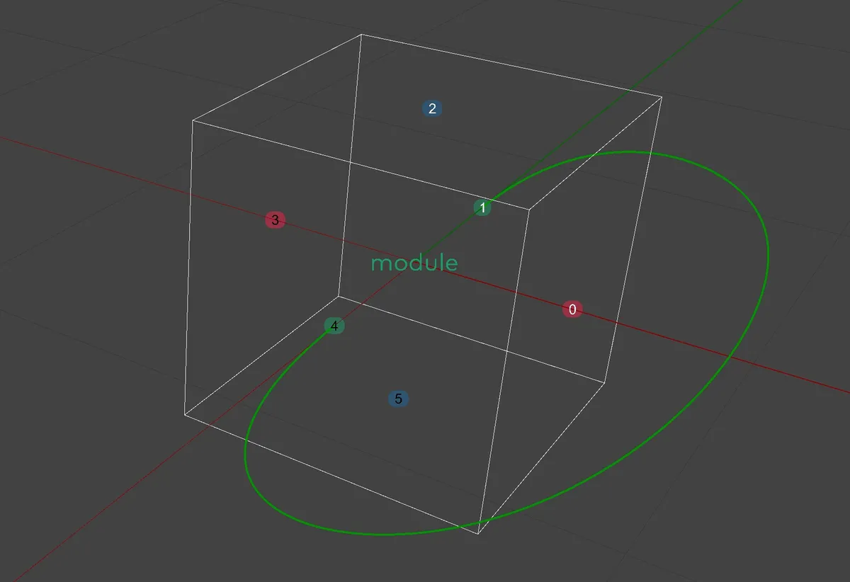
8.2.2. Connectors
The Module cages are subdivided to match the size of Envelope Slots in their
respective directions. The outer walls of a Module cage are considered to be
Connectors. Connectors are numbered from 0 to n-1, where n stands for
the
number of (outer) Connectors of the respective Module.
The Monoceros Modules are designed to connect to each other through their Connectors. To enable such connection it must be described by a Monoceros Rule. A Connector can occur in multiple Rules, allowing it to connect to multiple counter-Connectors, out of which one will be chosen by the WFC Solver. Each Connector must occur in at least one Monoceros Rule, otherwise the Connector cannot have any neighbor, therefore such Module cannot be placed into the Solution.
Monoceros Rules may allow connection of Connectors from the same Module or from two distinct Modules. A Rule, therefore also a connection, is only valid when the two Connectors are in opposite orientation of the same axis (i.e. negative Y can connect only to positive Y).
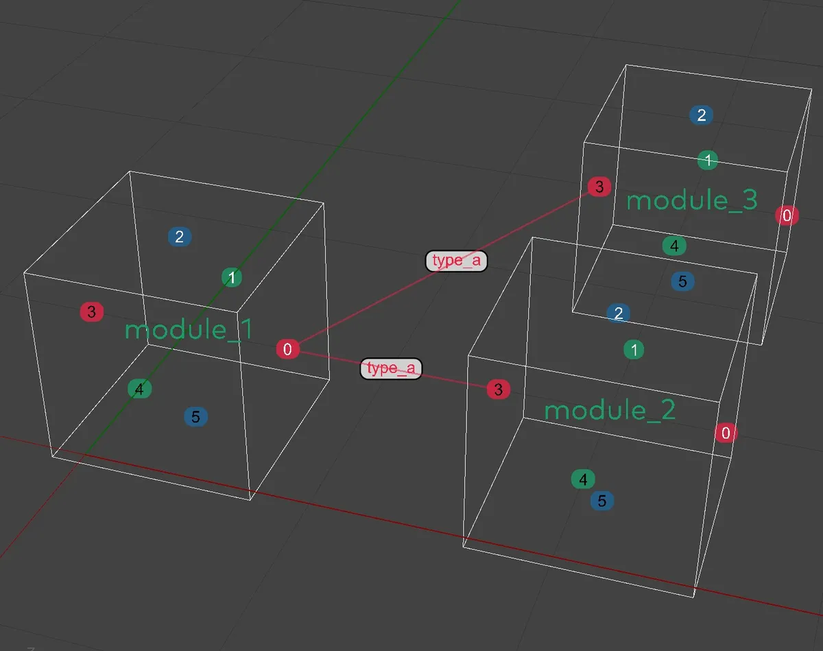
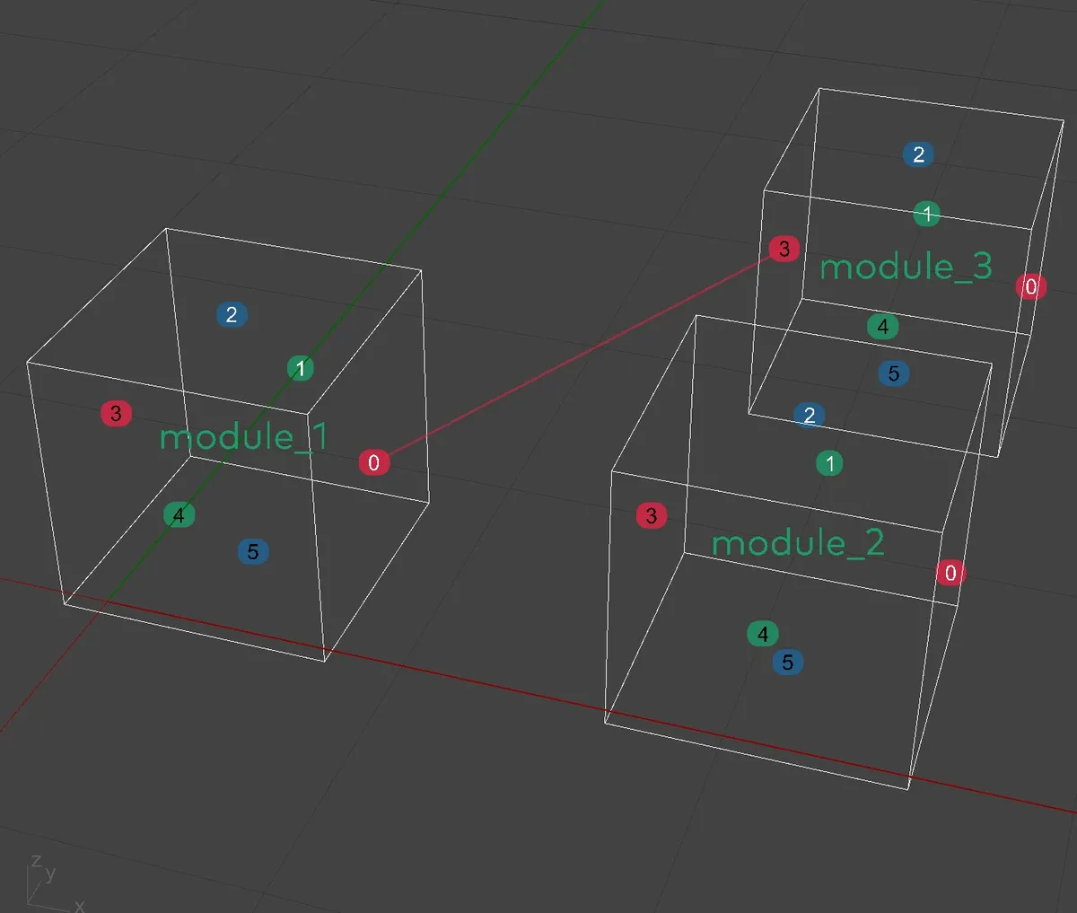
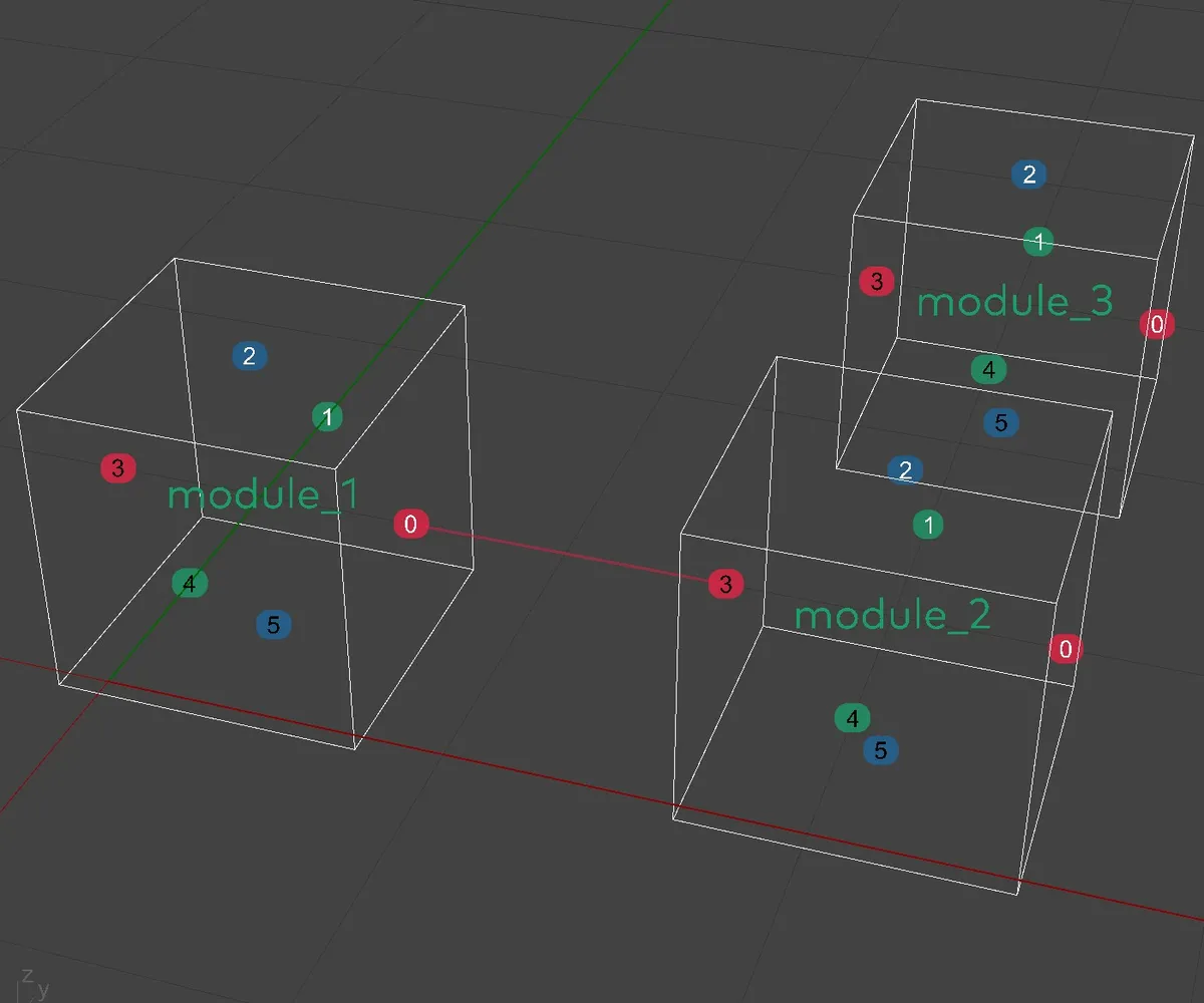
Monoceros Rules are referring to Module names and Connector Indices. The supplemental Monoceros components for constructing Rules use visual representation of Connectors (rectangles or dots) to identify the Rule being created.
8.2.3. Module Geometry
The purpose of a Monoceros Module is to place geometry into dedicated Slots. The Module data type is not bound to its geometry, which means the shape, size and location of Module geometry has no relation to the Parts of the Module or Slots it may occupy. This is an intentional feature because in real-life architectural and design applications, the Modules will need to posses extending parts (physical connectors) that would not fit the cages of Module Parts and therefore would compromise the WFC solution.
Therefore, the Module Geometry may be small, larger, different than the Module cage or remain completely empty.
Therefore a Module is being constructed from different input data than its Geometry. To mark Module Parts (Slots the Module may occupy) the user specifies Points inside these Parts. For convenience, it is possible to use Slicer helper component, that analyzes input geometry (no matter whether it is the same geometry that is being held by the Module or a different one) and returns exact centers of Slots that may be occupied by Module Parts.
8.2.4. Orientation and placement
A Module has a fixed orientation. When it is being placed into Slots it is only being translated (moved) and never rotated. There are maximum of 24 different discreet 90 degree rotations of an object. Rotating all Modules automatically would take a lot of control from the user. Therefore, if any rotation is desired, it has to be done manually by creating a new, different rotated version of the Module. The best way to do this it to rotate and adjust all input data (Module Part Points, Module Geometry) and give it a different name.
8.2.5. Module Properties
- Name - is a string unique identifier assigned by the user. The Name is automatically converted to lowercase. All Monoceros components with Module list input check if the Module names are unique. If not, they do not compute. The name is the sole identifier of a Module for all purposes, so that it is possible to replace a set of Modules within a solution with a different one.
- Module Part Center Points - center Points of Module Parts in cartesian coordinate system. The points are automatically calculated and can be used to create a new Module with the same Parts (cage) or to define the Slot Envelope exactly around the Module.
- Geometry - geometry to be placed into Slots with Materialize component.
- Base Plane defining Module's coordinate system. The discrete world coordinate system's origin and axial orientation matches that of the Base Plane. For a Module to be compatible with Slots, their Base Planes must match.
- Module Part Diagonal - defining Module Part's dimensions in X, Y and Z directions as defined by the Base Plane. For a Module to be compatible with Slots, their Diagonals must match.
- Connectors - reveals the Module Connectors as Planes tangent to the Connector rectangle, with Normal pointing outwards and origin at the Connector center. The Connector Indices (or their order in this list) does not represent their direction.
- Connector Directions - unit vectors aligned to the base plane indicating the direction of connector's normal (i.e. positive X direction is always {1, 0, 0}, negative Z is always {0, 0, -1}). Returns a list parallel to the list of Connectors.
- Connector Use Pattern - is a boolean list computed from the Module and the list all Rules indicating whether the Connectors have been already described by any Rule. The Monoceros WFC Solver requires each Module Connector to be described by at least one Rule, therefore it is important to generate some Rules for all unused Connectors before attempting to find a solution. Returns a list parallel to the list of Connectors.
- Is Compact - single boolean value indicating whether the Module Parts create a coherent compact continuous blob. If there are any gaps or Parts touching only with edges or corners, the Module is not compact. Such Module would not hold together in the WFC solution and therefore is automatically skipped by the Monoceros WFC Solver. It is allowed to construct such Module and to preview it in the viewport, so that the user can manually adjust the input parameters and construct a compact Module.
- Is Valid - internally, there are many reasons why a Module could be invalid, but only one reason is allowed to happen in Grasshopper: if a Module consists of too many Parts. The current upper limit is 256 Parts for all Modules combined. If a single Module outreaches this value, it is marked as invalid. It is allowed to construct such Module and to preview it in the viewport, so that the user can manually adjust the input parameters and construct a valid Module.
8.2.6. Special Modules: Out and Empty
There are two reserved Module names in Monoceros: Out and Empty. It is not allowed to manually construct a Module with such name, because they are being constructed automatically.
The Out Module is present in each solution. It is a Module with a single Part, exactly the size of a single Slot and holds no Geometry. It is automatically placed into Slots outside the user-defined Envelope. All Out Module Connectors are marked with Indifferent Rules, so any Module with an Indifferent Rule marked Connectors can be placed next to it - in other words, it enables the Indifferent Modules to be on the boundary of the Envelope. The Out Module does not render in preview, nor bakes.
The Empty Module with a single Part, exactly the size of a single Slot, no Geometry and all Connectors marked with Indifferent Rules has to be constructed manually with a dedicated Monoceros component. It behaves as any other Module because it is a regular Module that can be constructed also without the special Monoceros component. It render in viewport, it can be baked, so that individual Rules can be assigned to it. The Empty Module helps complex Monoceros setups to find a solution, because it fills the gaps between complex Modules and their Parts.
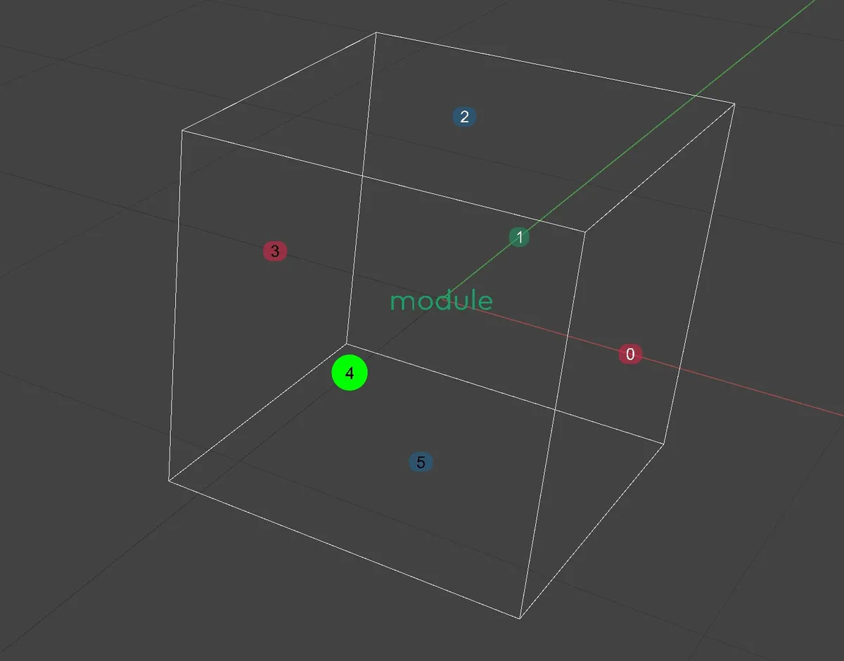
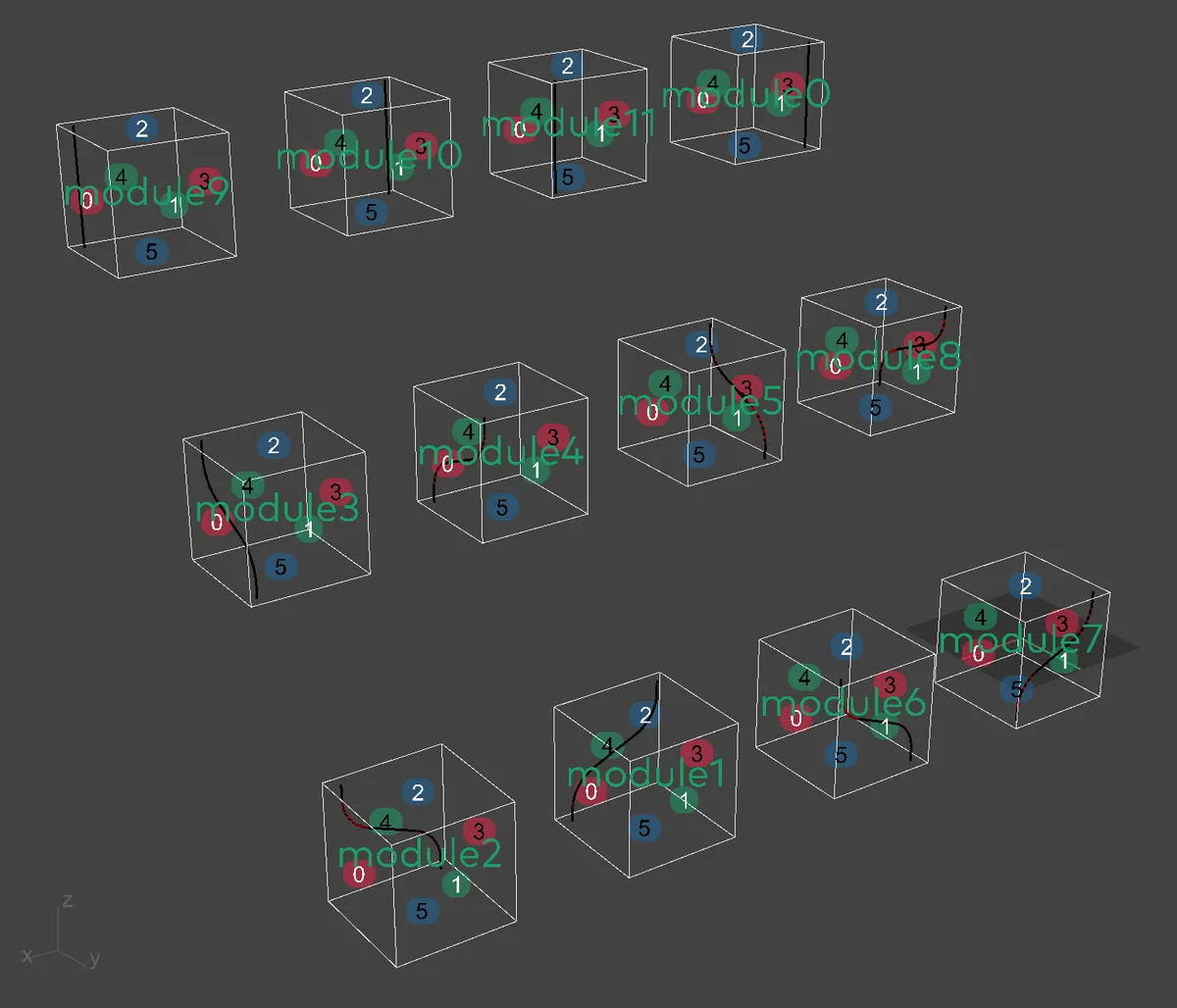
8.2.7. Viewport preview and baking
Module preview renders in Rhinoceros viewport with many helper items:
- Cage - boundary Connectors of Module Parts render and bake as wire frame rectangles. The Cage is white when the Module is valid, red when it is invalid because it is no compact or consists of too many Parts.
- Name - renders as a large text, green if the Module is valid, red it is invalid. The Module Name bakes as a text dot with the Name as a label.
- Connectors - render and bake as text dots with Connector Index as a label.
The dots are placed in the center of the Connector rectangle. The dots render
in colors indicating their direction:
- Red = X
- Green = Y
- Blue = Z
- White text = positive orientation
- Black text = negative orientation
- Geometry - renders as regular Grasshopper geometry but does not bake
The helper geometry preview does not follow the Grasshopper convention of a transparent green material for selected items and red for unselected.
The purpose of Module baking is to provide helper geometry and anchors for defining Monoceros Rules. It is possible to snap to Connectors or Cages to define a Rule graphically.
8.2.8. Module casts
Module casts help using the Module directly as an input to various components, even when they require a Module name, i.e. Rule or Slot Constructors.
- Module Name - is a special Monoceros data type that wraps a string name of a Module. Direct cast to a string is already taken by the user-friendly report, therefore the Module first casts its name to Module Name type, which then casts into text (string) for user-friendly report. Monoceros components, however, expect the Module Name type. This way it is possible to use the Module as an input where a Module Name is expected and there is no need to deconstruct the Module to its properties.
- Text (string) - returns a human-friendly report of the Module's properties
in format:
Module "XY" has XY connectors and has XY parts with dimensions XYZ.and eitherThe Module is compact.orWARNING: The Module is not compact, contains islands and therefore will not hold together.
8.3. Rule
Monoceros Rule is a distinct data type describing an allowed adjacency of two Modules by aligning their Connectors facing opposite direction. The Monoceros WFC Solver parses the Slots so that they only allow placement of Modules or their Parts that can become adjacent neighbors according to the Rule set.
Internally, the WFC Solver only works with Explicit Rules, but for convenience Monoceros offers also a Typed Rule. A Typed Rule is automatically unwrapped into one or more Explicit Rules by the WFC Solver and other supplemental components. Both types of Rules manifest as a single data type, can be processed together.
The Rule refers to Modules via their string (text) names and to Connectors via their integer indices. This allows the same Rule set to be used with a different (yet fully compatible) set of Modules.
A single Module Connector can be referred to by multiple Rules but at least one referring Rule is required.
In some cases the Modules cannot connect even though a Rule allows it because their Parts collide. Monoceros does not for check such cases because the WFC Solver itself prevents such situations from happening. That means that even though a Rule is valid, it may never occur in the solution.
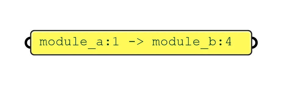
8.3.1. Explicit Rule
Explicit Rule is closest to the original WFC Rule. It refers to a Connector of
one Module that can connector to a Connector of another Module. Its textual
representation follows a pattern module:connector -> module:connector, i.e.
pipe:1 -> bulb:4, which translates to: Module "pipe" can become a neighbor of
Module "bulb" if their connectors 1 and 4 touch.
An Explicit Rule should only allow connection of two non-opposing Connectors, which makes the Rule invalid. Because Connector indices do not indicate their direction, it is only possible to check this when the respective Modules are provided. Therefore a full validity check is performed only when both data is available, most importantly in the Monoceros WFC Solver. When the Explicit Rule is created, it is only checked whether it refers to two different Connectors.
Explicit Rule is bi-directional, therefore a:1 -> b:4 equals b:4 -> a:1.
8.3.1.1. Explicit Rule properties
- Source Module Name - is the unique text identifier of the source Module
- Source Connector Index - is the unique integer identifier of the source Connector of the source Module
- Target Module Name - is the unique text identifier of the target Module
- Target Connector Index - is the unique integer identifier of the target Connector of the target Module
8.3.1.2. Explicit Rule casts
An Explicit Rule can be cast from a text (string) that has format identical to
the user-friendly Explicit Rule text report:
module:connector -> module:connector. An Explicit Rule does not casts to any
other data type.
8.3.1.3. Explicit Rule Viewport preview and baking
An Explicit Rule cannot be displayed on its own. Following a precedent of Vector display component in Grasshopper, there is a Rule Preview component in Monoceros. When provided with all Modules, it displays an Explicit Rule as a line between the connectors described by the Rule. The color of the line indicates the direction of the connectors (and therefore also of the Rule): red means the connectors are facing X direction, green represents Y direction and blue indicates Z direction.
An Explicit Rule preview can be baked.
8.3.2. Typed Rule
Typed Rule is a convenience data type introduced by Monoceros. It assigns a
"connection type" to a Connector of one Module, which then can connect to any
opposite Connector of any Module with the same "connection type" assigned by
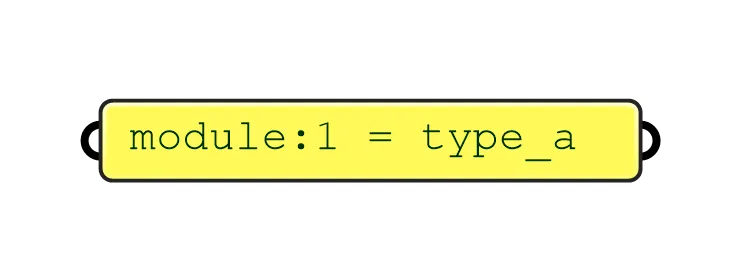
another Typed Rule. Its textual representation follows a pattern
module:connector = type, i.e. player:1 = jack, which translates to ` Module
"player" can become a neighbor of any Module if its connector 1 touches the
other Module's opposing connector if both connectors are assigned type "jack".
A Typed Rule needs to be unwrapped into one or more Explicit Rules before entering the WFC Solver. This is done automatically by the Monoceros WFC Solver component and by supplemental components such as Unwrap Typed Rules or Collect Rules. For Typed Rule unwrapping it is necessary to provide all Modules so that only opposing Connectors of the same type can unwrap into valid Explicit Rules. Even non-opposing Connectors can be assigned the same type. In such case, only valid (opposing) couples will be unwrapped into Explicit Rules.
As the Typed Rule is in fact a half-rule, it is always valid as long as it refers to an existing Module and its Connector.
8.3.2.1. Typed Rule properties
- Module Name - is the unique text identifier of the (source) Module
- Connector Index - is the unique integer identifier of the (source) Connector of the (source) Module
- Type - is the unique text identifier of the connection type. Two Modules with opposing connectors assigned the same connection Type can become neighbors.
8.3.2.2. Typed Rule casts
A Typed Rule can be cast from a text (string) that has format identical to the
user-friendly Typed Rule text report: module:connector = type. A Typed Rule
does not casts to any other data type.
8.3.2.3. Typed Rule Viewport preview and baking
A Typed Rule cannot be displayed on its own. Following a precedent of Vector display component in Grasshopper, there is a Rule Preview component in Monoceros. When provided with all Modules, it displays a Typed Rule as a line between all couples of opposing Connectors assigned the connection Type. The color of the line indicates the direction of the connectors (and therefore also of the Rule): red means the connectors are facing X direction, green represents Y direction and blue indicates Z direction. In 1/3 (to prevent collision because in real-life use cases lines cross in their middle) of the line there is a dot with a text label indicating the connection Type.
A Typed Rule preview can be baked.
8.3.3. Indifferent Typed Rule
For convenience, Monoceros introduces a built-in Rule type: indifferent. When
a Connector is marked Indifferent, it can connect to any other Indifferent
connector of any Module. The purpose of such Typed Rule is to indicate, that the
user does not care about specific adjacency of the given Connector and at the
same time to satisfy the WFC requirement, to describe each Connector with at
least one Rule.
Even the indifferent Rules need to be constructed manually using the Construct Typed Rule or simpler Indifferent Rule From Point. In the usual use case, the Indifferent Rule is assigned to those Connectors, that have not been described by any other intentional Rule. For such cases, there is a shorthand constructor component Indifferent Rules For Unused Connectors.
Just like any other Rule, Typed or Explicit, also the Indifferent Rule can be assigned to a Connector that already is described by another Rule. It can also be used as a disallowed Rule with the Collect Rules component.
9. Monoceros WFC Solver
Over the course of multiple iterations (called observations) occurring internally inside the WFC Solver, Wave Function Collapse gradually changes the state of Slots from non-deterministic (allowing multiple Modules) to deterministic (allowing exactly one Module). This iterative process happens in the Solver component, where the Slots are observed based on pseudo-random numbers until either every Slot ends up in a deterministic state (success), or any Slot ends up in a contradictory state (failure). If the result is contradictory, the Solver component internally re-tries up to a predefined number of attempts, each attempt using the already modified random state and thus producing a different result each try.
As mentioned earlier, Monoceros builds on top of the original Wave Function Collapse to make it more useful for architecture and industrial design. The essence of the Monoceros extension is how it treats Modules. In original Wave Function Collapse a Module always has the dimensions to occupy exactly one Slot. While Monoceros Modules are aligned to the same discrete grid, they can span multiple Slots and be of any voxel-based shape as long as their Parts connect in a continuous fashion - i.e. they touch with faces and not just edges. A Monoceros Module Part (not available as public data type) is equivalent to a vanilla WFC Module.
9.1. Rule and Module Lowering
Because it is not immediately clear how to implement a solver for Modules as defined by Monoceros, Monoceros utilizes a technique called lowering (sometimes also called desugaring) to change their representation into lower-level, vanilla WFC Modules and also produce metadata necessary to reconstruct the Monoceros Modules from the vanilla Modules.
Even though not visible to the user, Module Parts are carefully tracked throughout the plug-in, and since Rules effectively work with Module Parts already, the Grasshopper Solver lowers the Module and Rule definitions into their low-level forms and feeds those into the Rust solver over the C API. After the Rust solver finishes successfully, Monoceros Modules are reconstructed from its output thanks to the backwards mapping metadata generated by lowering.
9.2. 1.7.2 Canonical World State
Because Monoceros allows us to modify and customize the initial state of the world and vanilla WFC has an opinion on how valid world state looks like, the Rust solver needs to detect whether the world is Canonical (valid in terms of vanilla WFC).
A world is Canonical if:
-
Every Slot allows every Module (this is the initial WFC world state),
-
The world is a result of applying both the observation and subsequent constraint propagation phases on an already Canonical world.
For example, running an observation without subsequently propagating does not produce a Canonical world and WFC does not define how this world should behave if observed or propagated any further.
Setting the state of the world manually rarely produces a Canonical world. Therefore the Rust solver always Canonicalizes the world before running an observe/propagate operation. Canonicalization is implemented by starting the constraint propagation phase on every Slot as though it was just observed. This process can in theory be expensive, but fortunately needs to run just once per invocation of the Solver component. The Rust solver provides the information whether the world needed canonicalizing as part of its output.
11. Examples
11.1. Bare minimum
11.1.1. Pseudo code
- construct (one or) more Slots
- construct one or more Modules
- define Rules for each Connector of Each Module
- run Monoceros WFC Solver
- Materialize the result
11.1.2. Definition
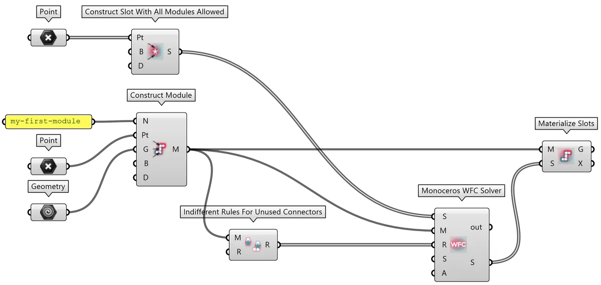
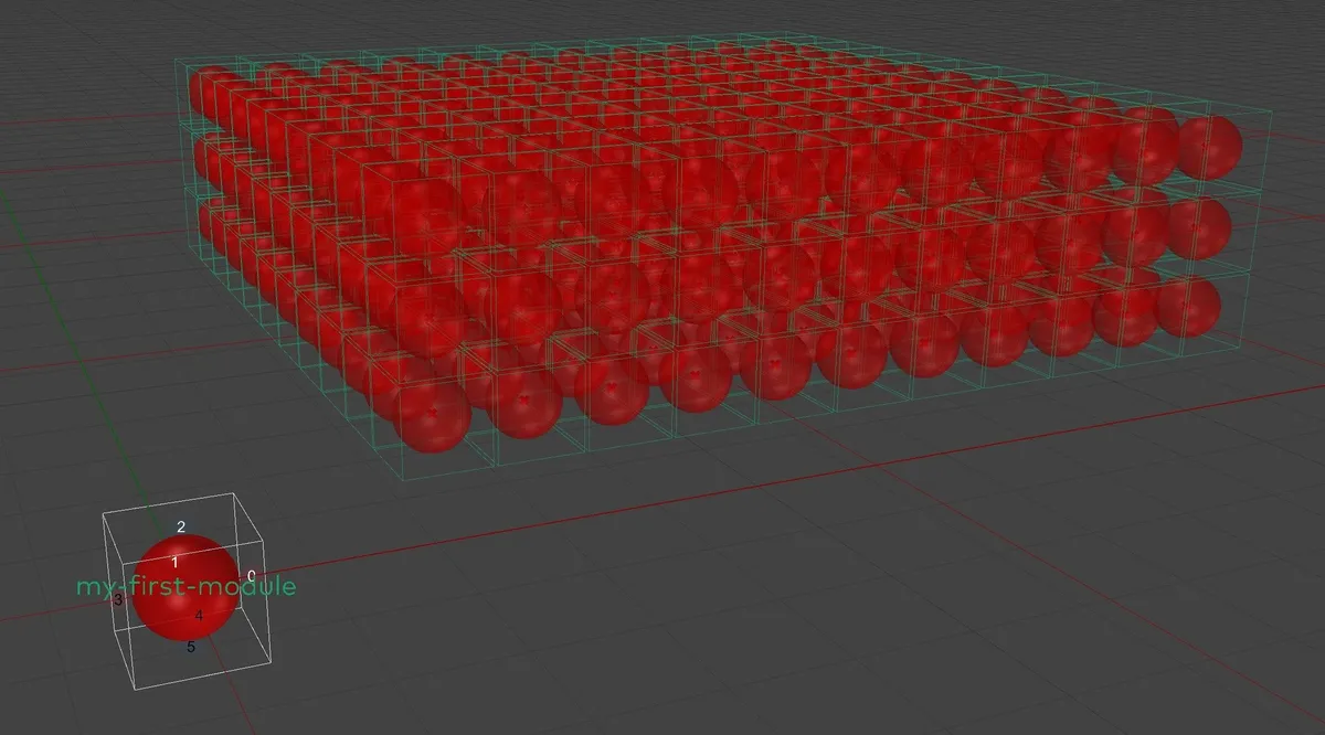
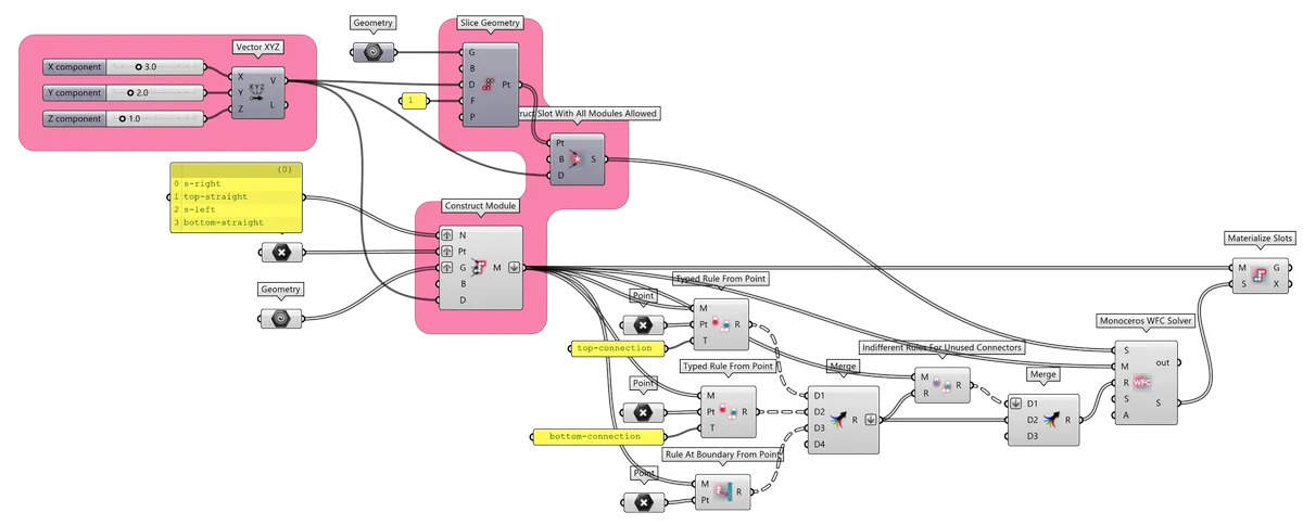
11.1.3. Breakdown
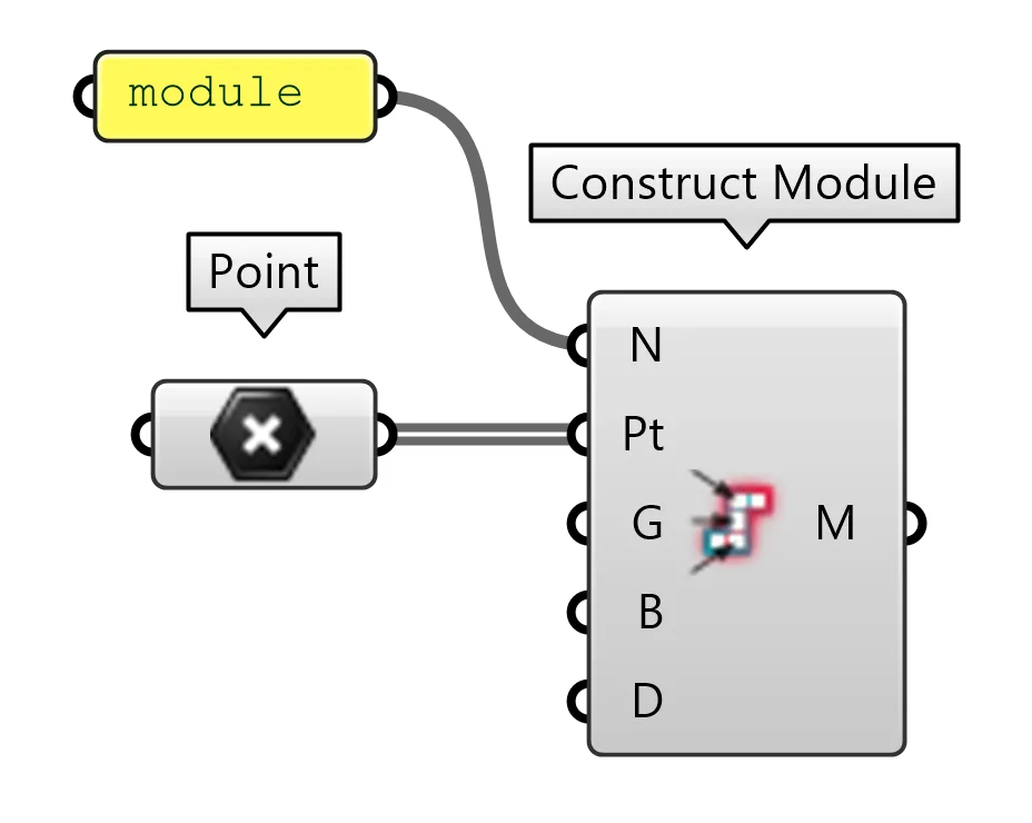
- Construct Slot With Listed Modules Allowed constructs Monoceros Slots that allows placement of any Monoceros Module. Input Points collects points placed inside the created Slots. If two of such points are inside the same Slot, such Slot will be constructed twice. Therefore it is recommended to deduplicate input points. The Output contains as many Slots as there are input points.
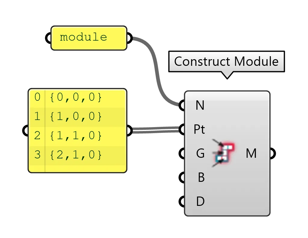
- Construct Module constructs a single Monoceros Module. Input Name collects unique Module name. Input Points collects points inside Module Parts. The points do not need to be deduplicated. Input Geometry collects geometry that should be placed into respective Slots by the Materialize Slots component.
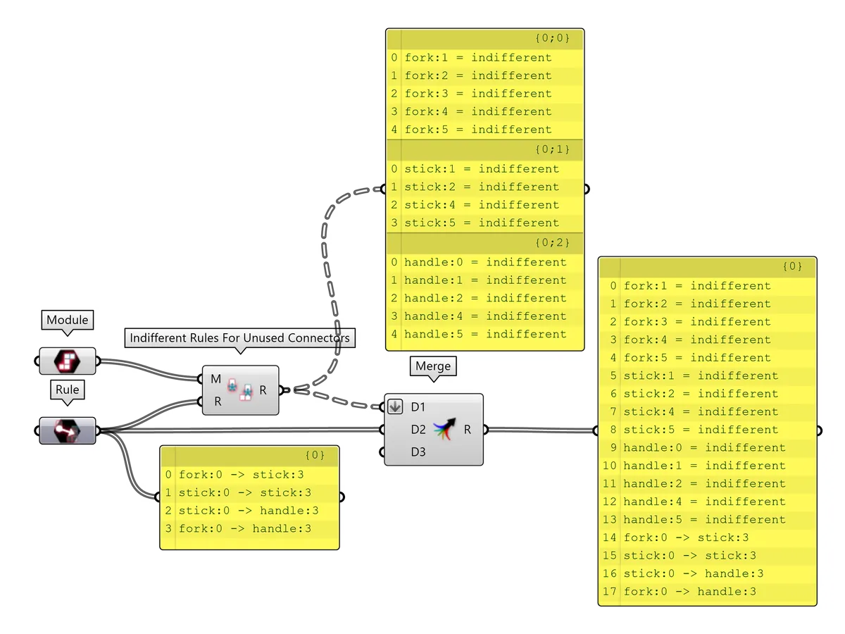
- Indifferent Rules For Unused Connectors generates Indifferent Typed Rule for all Module Connectors from the Input Modules that are not described by any of the Rules collected from the Input Rules. In this case there are no preexisting Rules, therefore all Module Connectors will be assigned an Indifferent Rule. The Output contains a single Rule for each unused Module Connector. For more information see the Indifferent Rules example.
- Monoceros WFC Solver parses the Envelope defined by the Input Slots, according to Input Rules that apply to Input Modules. If successful, the Output contains Slots that are deterministic and contain exactly one Module.
- Materialize Slots components places Input Modules' Geometry into Input Slots into which they belong.
11.2. Explicit Rules
Explicit Rules describe a one-to-one connection between two Module Connectors. The Connectors may come from a single or from more Modules.
An Explicit Rule is valid when the two Connectors are opposite in the same axis (i.e. positive X connects to negative X). The validity check is only performed in components that require both, Modules and Rules as an input. Invalid Rules are being omitted.
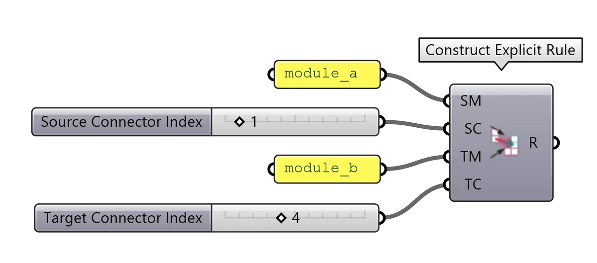
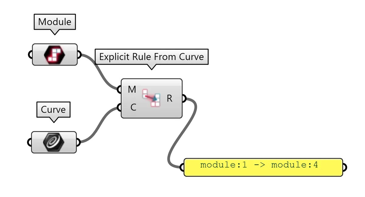
An Explicit Rule can be constructed as a literal (from Grasshopper text Panel), from its components (source and target Module and Connector Index) using Construct Explicit Rule component, from a Curve connecting source and target Connector using Explicit Rule from Curve component or with Rule at boundary from Point component, that creates an Explicit Rule connecting the Module Connector with an implicit Out Module residing outside the Envelope.
Note: It is possible to use Module type data as Module Name.
11.2.1. Definition: Explicit Rule from a literal
11.2.2. Definition: Explicit Rule from components
11.2.3. Definition: Explicit Rule from curve
11.3. Typed Rules
Monoceros WFC Solver, Unwrap Typed Rules and Collect Rules generate Explicit Rules for all opposing Module Connectors marked with the same connection Type in the set of Typed Rules.
A Typed Rule is valid if it refers to an existing Module and its Connectors. The validity check is only performed in components that require both, Modules and Rules as an input. Invalid Rules are being omitted.
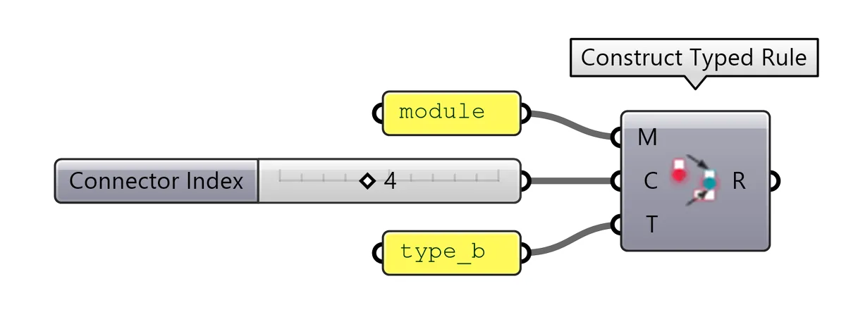
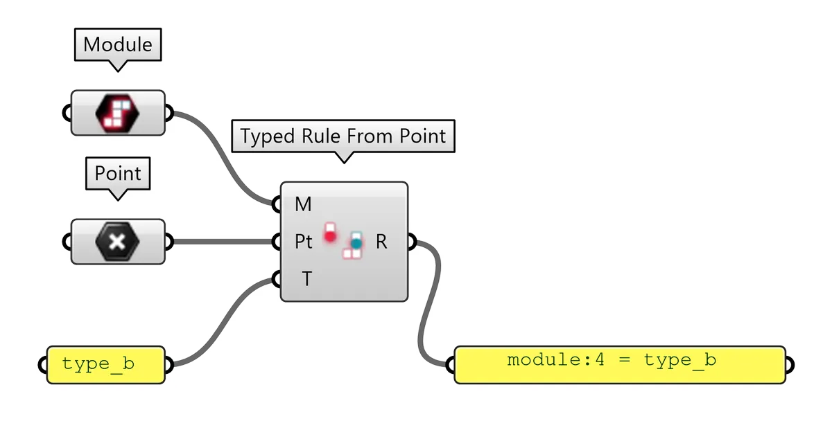
Typed Rules can be constructed from a literal (Grasshopper text Panel), from its components (name, Connector Index, connection Type) using Construct Typed Rule, from a Point tag (point inside the geometry of a Connector) using Typed Rule from Point or with shortcut components Indifferent Rule from Point and Indifferent Rule for unused Connectors. The second output of the Construct Empty Module component is also a list of Typed (Indifferent) Rules.
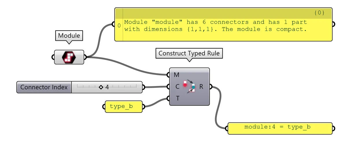
Note: It is possible to use Module type data as Module Name.
11.3.1. Definition: Typed Rule from a literal
11.3.2. Definition: Typed Rule from components
11.3.3. Definition: Typed Rule from components using Module as Name
11.3.4. Definition: Typed Rule from Point tag
11.4. Indifferent Rules
Indifferent Rules are ordinary Typed Rules with a predefined Type indifferent.
It is a reserved Type because the Out and
Empty Modules have all connectors
automatically described with Indifferent Typed Rules (in case of Empty Module,
the Rules need to be added manually to the Rule set). Any Connector described
with the Indifferent Rule can connect to any opposite Connector described by an
Indifferent Rule. This is mostly used for those Connectors that represent
geometrical back or side (do not have a physical connector) of a Module and the
user does not have any specific intention with them. Indifferent Connectors can
be placed on the boundary of the
Envelopebecause the Out Module has all 6
Connectors described as Indifferent.
The Monoceros WFC Solver requires each Module Connector to be described by at least one Rule and the Indifferent Rule is a good option for those Connectors that do not have any other purpose.
A connector can be described as indifferent even if it is described by another Explicit or Typed Rule. In most cases, only the unused Connectors are being described as Indifferent. There are several ways of constructing Indifferent Rules for unused Connectors.
For the Monoceros WFC Solver component you need to Collect or simply Merge all Rules - the manually assigned ones with the generated Indifferent and Rules coming along with the Empty Module.
11.4.1. Definition: Indifferent Rules for unused Connectors
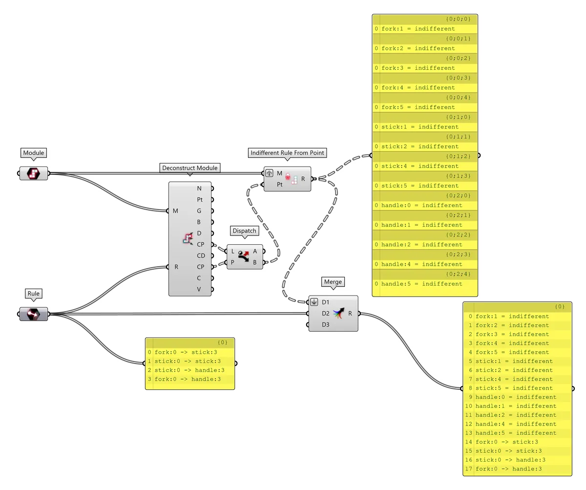
11.4.2. Definition: Indifferent Rules manual assignment
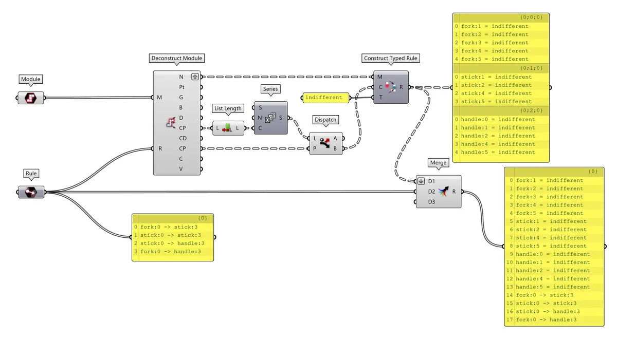
11.4.3. Definition: Indifferent Rules literal assignment
11.5. Defining more Modules at once
11.5.1. Pseudo code: (almost) without data trees
- construct Slots
- construct each Module individually with one or more Geometry
- define Explicit Rules from Curves
- define Indifferent Rules for unused Connectors
- merge and flatten all Rules
- run Monoceros WFC Solver
- Materialize the result
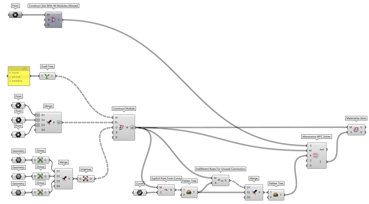
11.5.2. Definition: (almost) without data trees
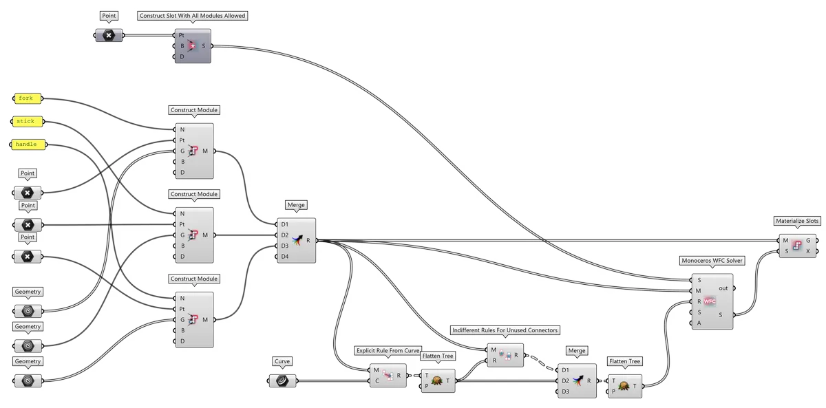
11.5.3. Pseudo code: with data trees
- construct Slots
- graft list of Module names so that each name ends up in a separate branch
- merge Module Part Points and graft so that each Point ends up in a separate branch (if a Module consists of multiple Parts, process the Points like the Geometry in the following steps)
- if one or more Modules should contain more Geometry items, group each Geometry items belonging to each Module (do this also for single Geometry items), then merge to get a list of groups and ungroup so that each list of Geometries ends up in a separate branch
- construct Modules at once using the parallel data trees of Names, Points and Geometries
- flatten the list of Modules
- define Explicit Rules from Curves
- define Indifferent Rules for unused Connectors
- merge and flatten all Rules
- run Monoceros WFC Solver
- Materialize the result
11.5.4. Definition: with data trees
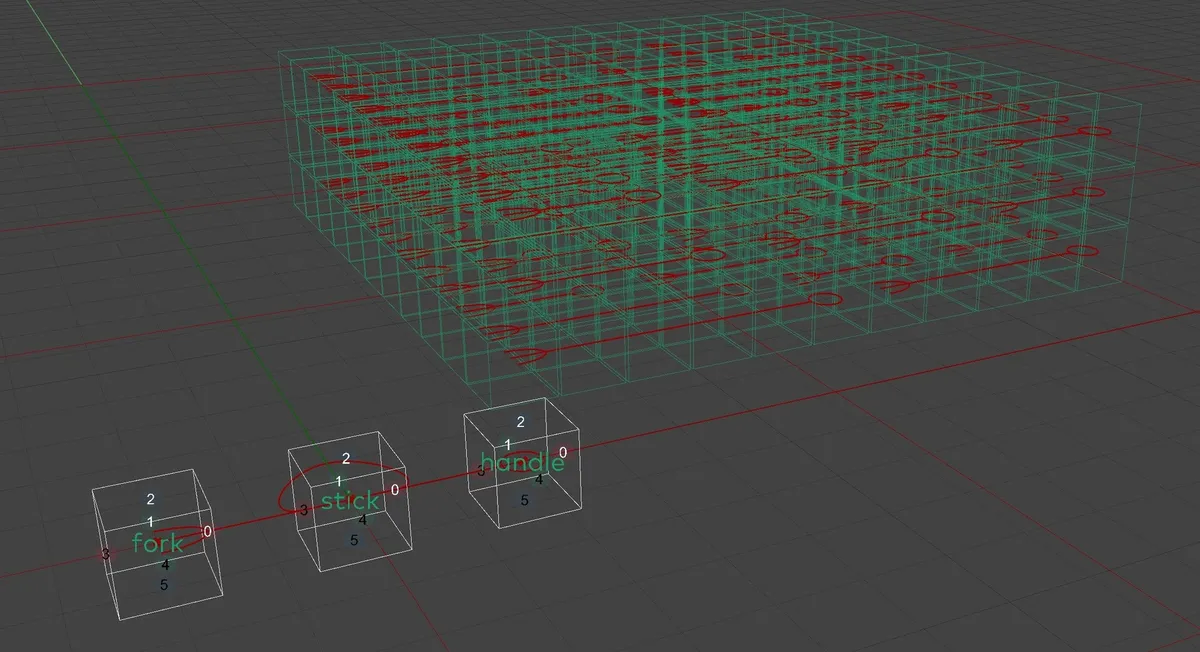
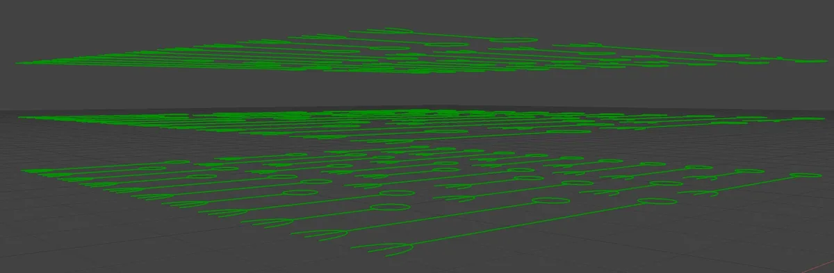
11.5.5. Result
11.6. Slots and Module Parts with non-uniforms dimensions
If the Module geometry does not naturally fit into cubic grid, it is possible to define a non-uniform grid for Module Parts as well as for the Slots. The dimensions of Part and Slot are defined as a Vector representing a diagonal of the basic grid unit. The axial dimensions of the Vector are aligned with the Module's or Slot's Base Plane.
The Diagonal also defines the discrete step of the world, in which the Modules and Slots reside. Therefore components Construct Module, Construct Slot with all Modules allowed, Construct Slot with listed Modules allowed and Slice Geometry consider the defined Base Plane as the world origin and orientation and the Diagonal as the basic unit, into which they should slice the WFC data.
All Modules and Slots used in one solution must have identical Diagonal dimensions!
11.6.1. Definition
11.6.2. Result
11.7. Modules and Envelope with individual base planes
A Base Plane defines element's (Module or Slot) coordinate system origin and orientation. All their coordinates and directions will be measured from the Base Plane.
During Materialization of the solution, the Module Geometry will be oriented from the Module Parts' Pivots (planes in the center of Module Parts aligned to the Module's Base Plane) to the respective Slot's Pivot (plane in the center of the Slot aligned to the common Base Plane of all Slots).
Even though in Monoceros it is possible to set individual Base Planes for each element, all Slots entering the Monoceros WFC Solver must share an identical Base Plane. The Modules can have individual Base Planes that do not need to be identical across the solution.
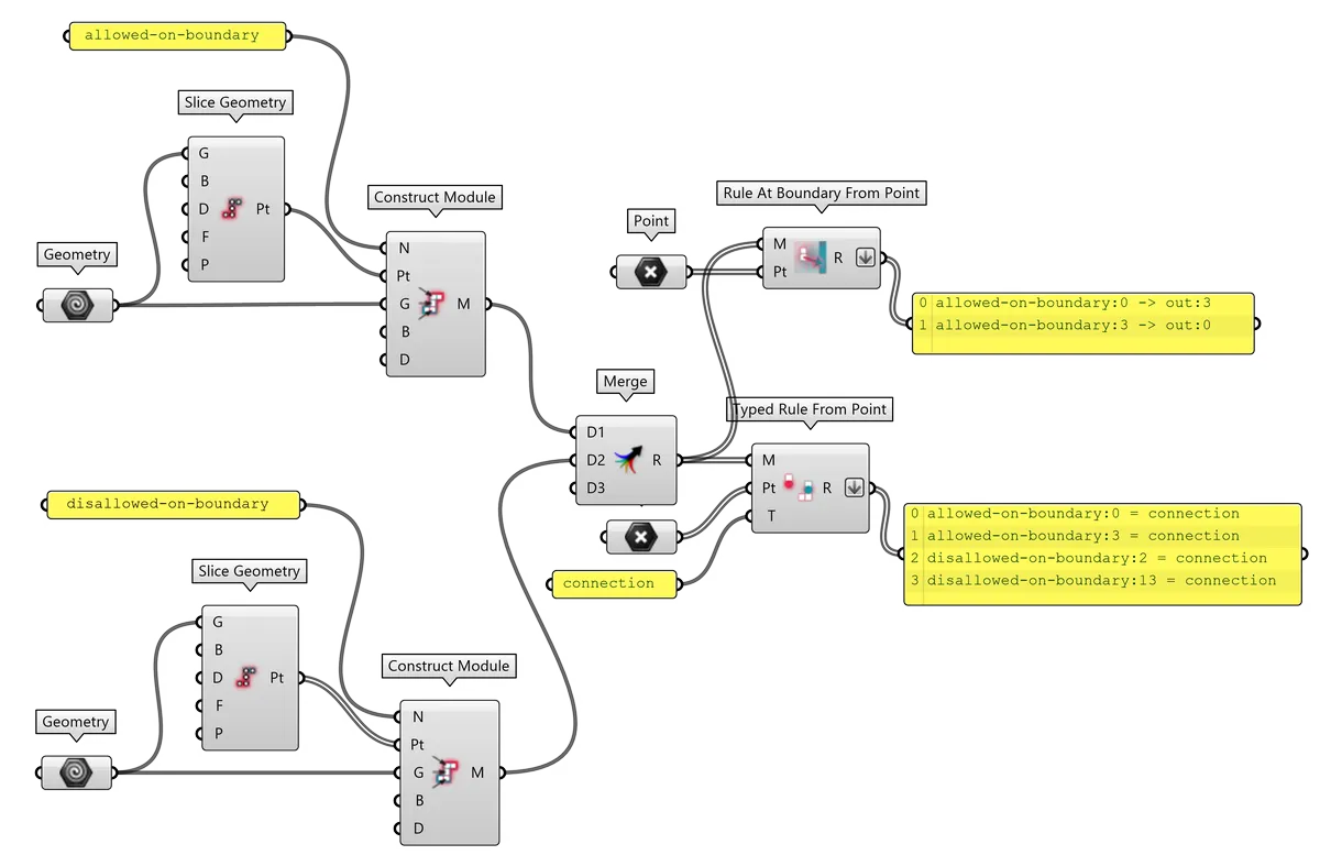
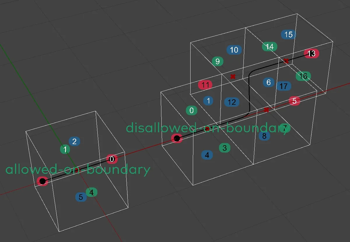
11.8. Disallowing Rules
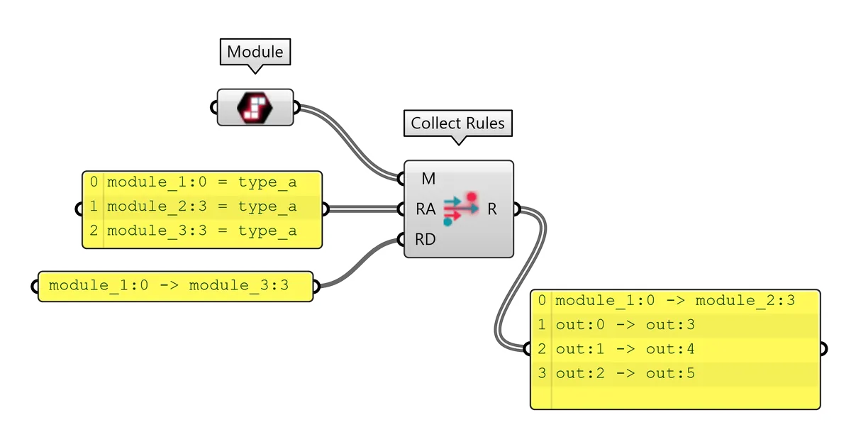
The Monoceros WFC Solver only works with allowed Rules, however sometimes it may be useful to disallow certain connection. This is especially useful when Typed or Indifferent Rules are being used. Such rules unwrap into one or more Explicit Rules, out of which some may be unwanted. In such case it is possible to remove the unwanted Rules from the rule set using the Collect Rules component and effectively disallowing them. If a Rule is not present in the collection of allowed Rules, it is not necessary to manually disallow it.
To disallow a Rule, it first needs to be created. Only then it is decided, whether the Rule will be allowed or disallowed:
- If a Rule should be allowed, it may be passed directly into the Monoceros WFC Solver or into the Allowed Rules input (and must not be passed into the Disallowed Rules input) of the Collect Rules component.
- If a Rule should be disallowed, it cannot be listed in the Rule set passed directly into the Monoceros WFC Solver. To ensure its removal from the list of allowed Rules, it should be passed into the Disallowed Rules input of the Collect Rules component, while all allowed Rules are being passed into the Allowed Rules input. The Collect Rules component first unwraps and validates all allowed and disallowed Rules and then removes (if present) the disallowed Rules from the list of allowed Rules.
Both, Explicit and Typed Rules can be disallowed. The Collect Rules component can be used repeatedly but in most cases it is enough to use it right before passing the Rules into the Monoceros WFC Solver because at hat time the list of all allowed Rules should be already complete.
The output of the Collect Rules component completely replaces any previous Rule set and should not be merged with any previous lists of Rules.
The Monoceros WFC Solver requires all Module Connectors to be described by at least one Rule. Disallowing Rules may result in removing all Rules for certain Connectors, which makes the solution impossible. In such case the Monoceros WFC Solver throws an error.
Note: The Collect Rules component automatically unwraps Typed Rules and adds Rules for Out Modules.
11.8.1. Definition
| Allowed Rules | Disallowed Rules | Resulting Rules |
|---|---|---|
 |
|
|
11.9. Modules with more Parts
A Module can consist of more Parts which always hold together in Materialized result of the Monoceros WFC Solver. Each Part should occupy one Slot of the world Envelope. The Construct Module component requires a list of Module Part Points inside the created Module Parts.
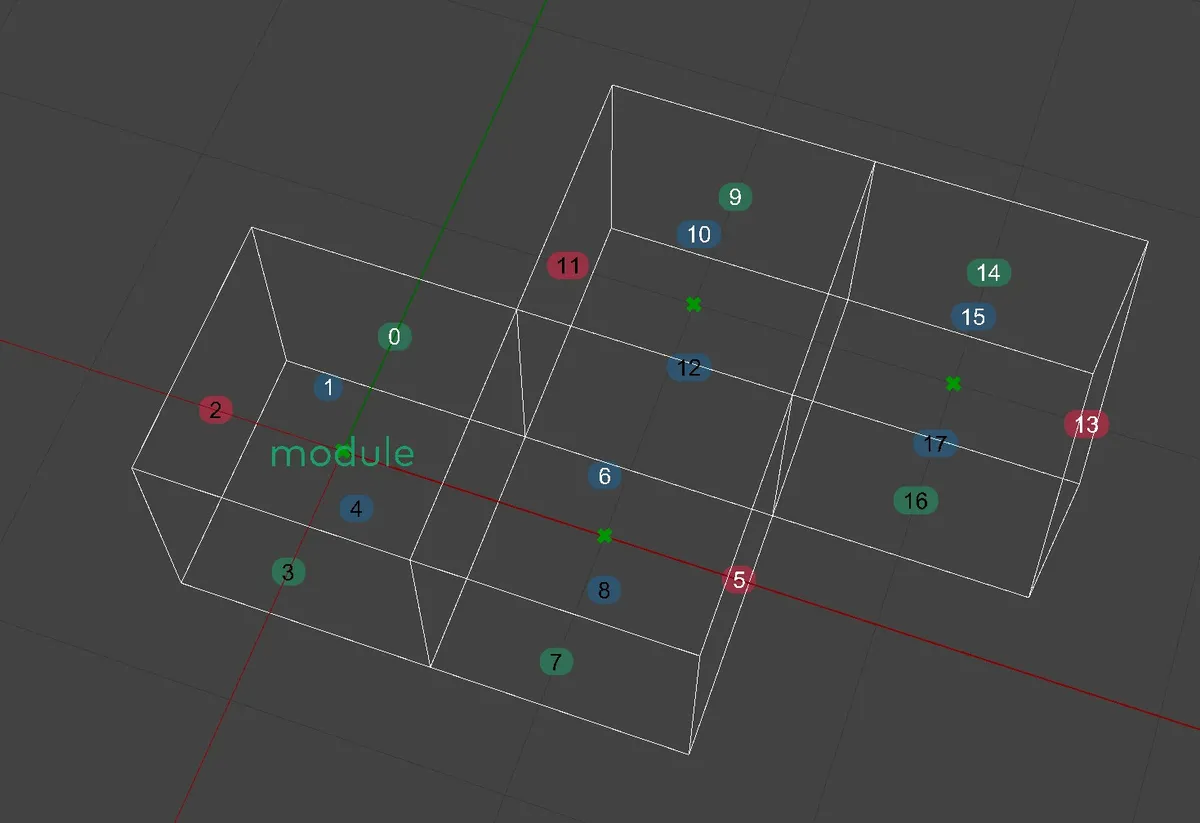
Potential Module Parts are boxes of a size specified as Diagonal filling the entire world, starting with a Part which has its center at the world origin defined by the Module's Base Plane, aligned to match the Base Plane orientation. Those potential Parts, which contain one or more Module Part Points will become Parts of the created Module. It means, that even more Points may mark a single Module Part and therefore the Points do not have to be deduplicated.
The Module Parts and therefore also the Module Part Points do not need to match the Module Geometry. In many cases the Module Geometry extends, occupies only some Module Parts or does not exist at all.
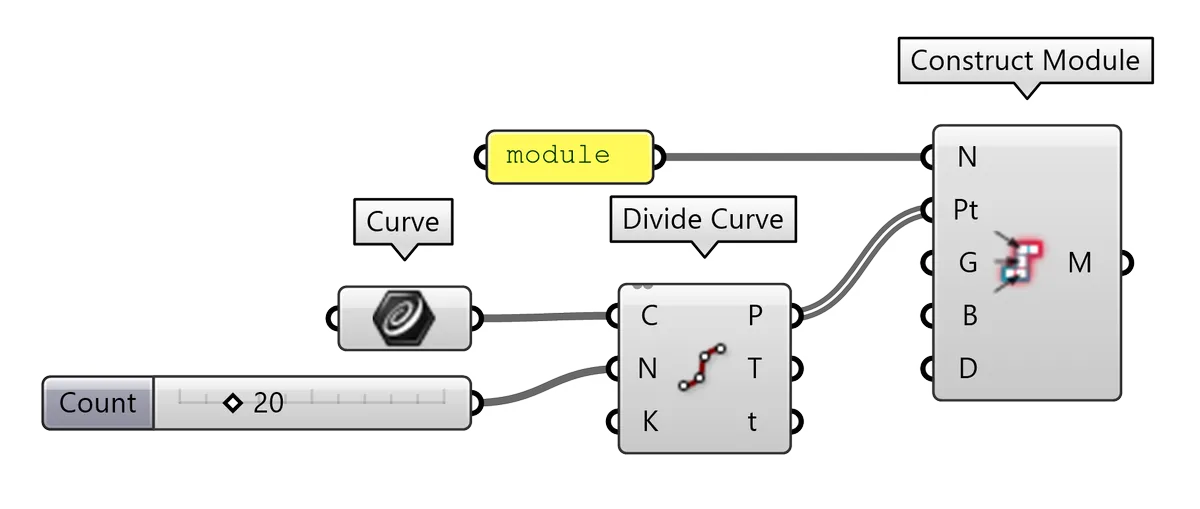
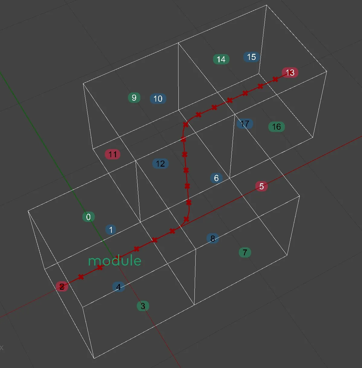
Module Part Points can be created manually, come from manually populated input geometry or from Slice Geometry component. It is recommended to create the Module Part Points manually whenever possible because it is the conscious way, whereas the Slice Geometry component is a brute force approach with many limitations and potentially inconsistent results.
It is recommended to keep the number of Module Parts meaningfully low. Too many Parts result in slow performance of the Monoceros WFC Solver and lower probability of finding a valid solution. The current version of the Monoceros WFC Solver also only supports solutions with maximum of 256 Parts from all Modules together. If this number is exceeded with a single Module, the Module is marked Invalid an the user gets notified by the Constructor and by all components and floating parameters receiving the invalid Module. If this number is exceeded only when all Modules are passed into the Monoceros WFC Solver, the user gets notified by the Solver component.
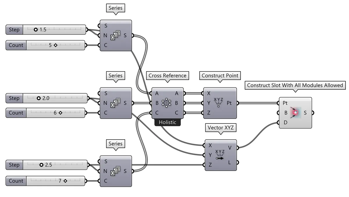
11.9.1. Definition: Module Part Points created manually
11.9.2. Definition: Module Part Points created manually from geometry
11.9.3. Definition: Module Part Points created with Slice Geometry
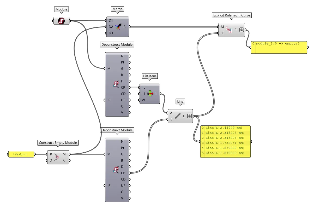
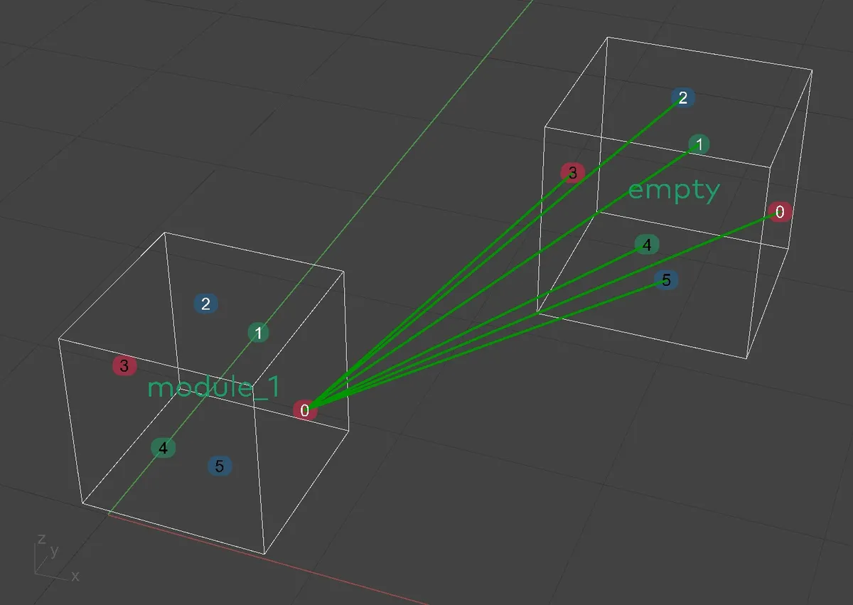
11.10. Empty Module and allowing an Empty neighbor
If the Modules consist of more Module Parts it is often possible that the Modules cannot be stacked together without leaving blank Slots, which is considered a contradictory and therefore invalid result.
Monoceros therefore introduces a convenient
Empty Module
constructor. It is a shortcut for creating a
Module named empty with a single Part, with no
Geometry and all Connectors described
as Indifferent. Since the name empty of the
default Empty Module cannot be changed, only one Empty Module can be used for a
solution.
Note: An Empty Module with a different name can be also constructed manually, which in some cases may be useful, when more types of empty Modules are required.
The Rules generated by the Empty Module constructor component need to be added to the Rule set.
An Empty Module does have a geometrical representation and does appear in the Rhinoceros viewport just like any other Module. Its helper geometry (cage and Connector anchor points) can be baked and used to define additional Rules involving the Empty Module, i.e. an Explicit Rule allowing adjacency of the Empty Module to a specific (non-indifferent) Connector or a Typed Rule.
Note: It is recommended to construct the Empty Module with a Base Plane shifted away from the world XY origin because in most cases there already is a custom module at {0,0,0} coordinate. If the Module inputs overlap, the Rules from Points or Curves may be mixed.
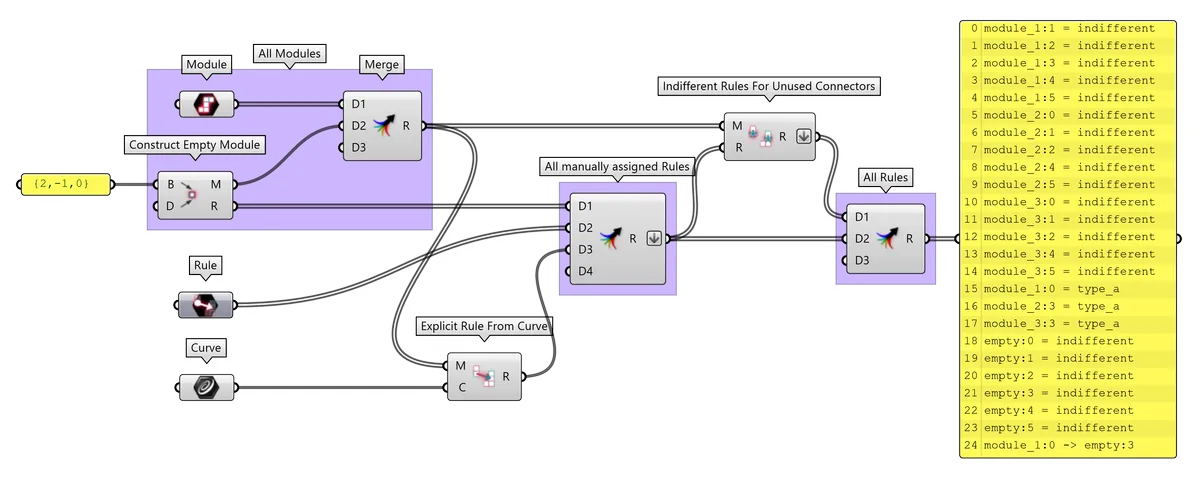
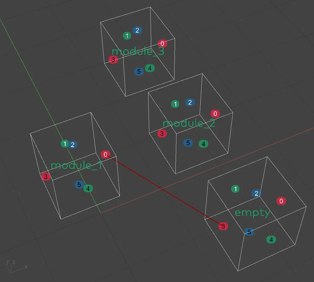
11.10.1. Definition: Empty Module and additional Explicit Rules
11.10.2. Definition: Explicit Rules with all Connectors of Empty
It is convenient to try to generate Explicit Rules from Curve from the desired Connectors to all six Connectors of the Empty Module. The Explicit Rule from Curve component, the Monoceros WFC Solver or other components will remove the invalid Rules that connect non-opposite Connectors and only keep the valid ones.
Note: This strategy can be applied onto any collection of Modules, not only onto the Empty Module.
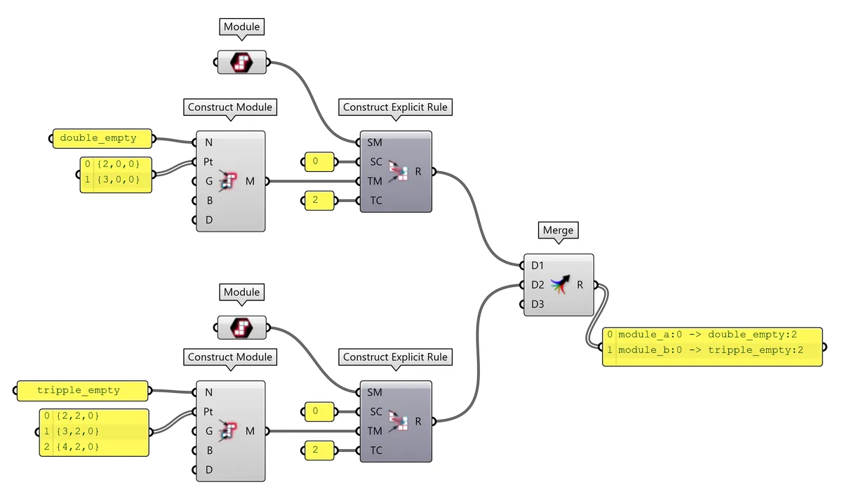
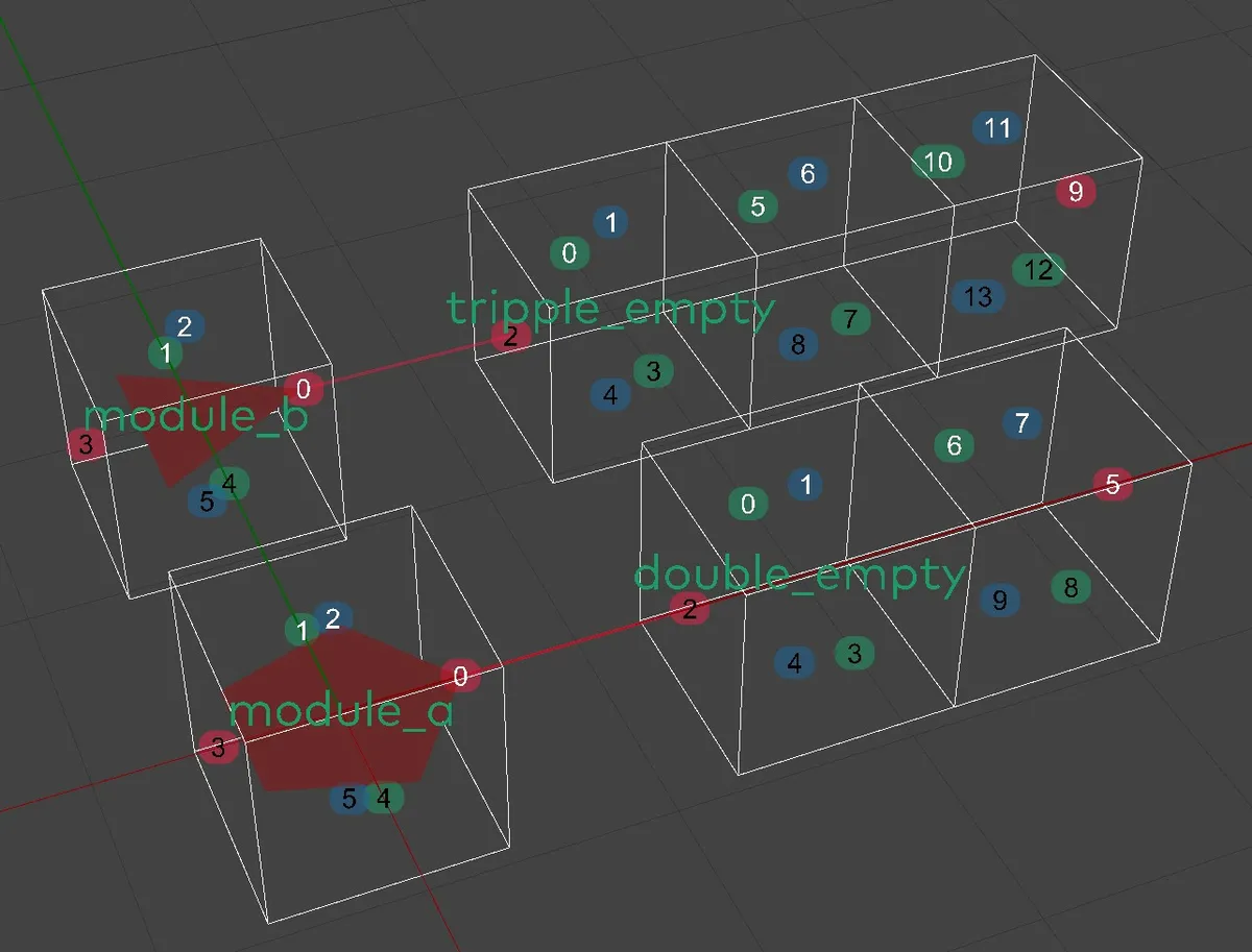
11.10.3. Definition: Multiple different Empty Modules
If the Empty Module should be larger than a single Part, it is convenient to generate custom Modules with no geometry with the required properties and allow them to be adjacent to the Modules that require more Empty space next to them.
Note: The Empty Module is often a way to make the setup valid. Replacing it with a custom empty module with multiple Parts may make the setup unsolvable.
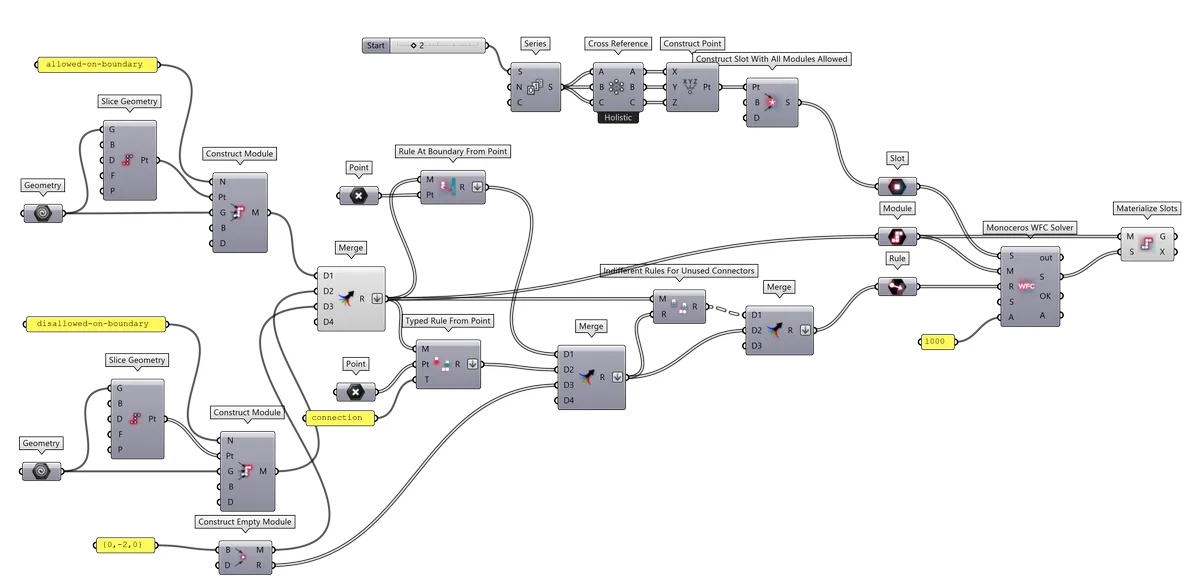
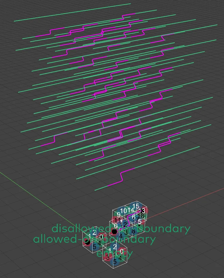
11.11. Allowing Modules to be at the boundary of the Envelope
The Envelope Slots are
automatically wrapped into a layer of Slots
containing exclusively an out Module. It is being generated
implicitly automatically in the
Monoceros WFC Solver component and in
Unwrap Typed Rules and
Collect Rules components. The Out Module has one Part and
automatically comes with all 6 connectors described as
Indifferent.
This way the Out Module can be adjacent to itself and to all Indifferent Connectors. That means that all Modules with Indifferent Connectors can be at the boundary of the Envelope because their Indifferent Connectors can be adjacent to the Out Module, which is certainly placed outside of the Envelope.
Some sets of Modules and Rule sets, however, require additional way of allowing some Modules to be at the boundary of the Envelope. THis typically happens when the Modules create an open linear (i.e. pipes) or a branching (i.e. growing tree) structure. Ins such case a Module that can appear in the middle of an assembly, should be also able to appear at its beginning and end - at the boundary of the Envelope. Such Module's Connector should not be described as Indifferent because then it could appear next to any other Indifferent Connector, which would break the structure of the aggregate. For such cases there is Rule at boundary from Point component, which creates an Explicit Rule, allowing adjacency of a Connector tagged with the input Point and an opposite Out Module's Connector. This is the most convenient way of creating such Rule because there is no need to specify the correct opposite Connector of the Out Module.
Note: The Out Module module does not have any geometrical representation in the Rhinoceros viewport and therefore it is impossible to create an Explicit Rule from Curve with it.
It is also possible to disallow certain Indifferent Module Connectors from appearing at the boundary of the Envelope by generating respective rules with the Rule at boundary from Point component and disallow them using the Collect Rules component.
11.11.1. Definition
11.12. Constructing Slots
Monoceros Slots are cuboid (box-like) chunks of space, delimiting a single basic discrete gid unit, which can contain certain Module Part. A flat list of Slots forms an Envelope. The Envelope can have any shape, be full or hollow, one, two or three-dimensional, form a single or multiple blobs.
Each individual Slot is created by defining (any) point inside the respective chunk of space delimited by the potential Slot. Each input point generates one Slot, therefore duplicate input points create duplicate Slots.
Slot input points can be constructed either manually, manually from geometry, using the Slice Geometry component or employing a combination of these methods. It is recommended to generate the input points manually or manually from geometry whenever possible because it offers better control. The Slice Geometry component is a brute force approach with many limitations and potentially inconsistent and imprecise results.
All described slicing methods apply also to constructing the Modules.
11.12.1. Definition: Slots from manually generated points
11.12.2. Definition: Slots from manually generated points from geometry
The fastest way to deduplicate manually generated points is to use the Slice Geometry component.
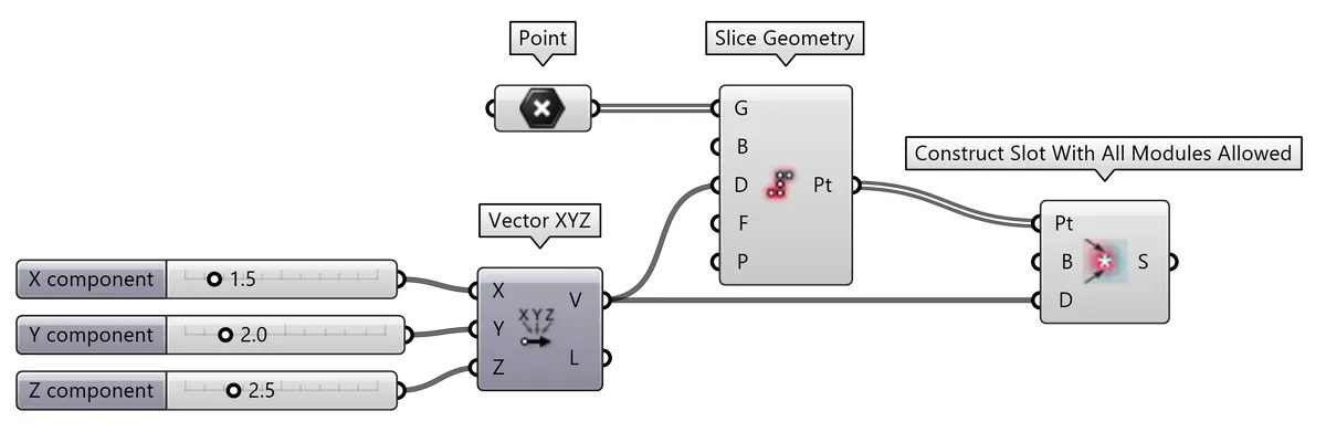
11.12.3. Definition: Slots from Slice Geometry: Points
Monoceros Slots are constructed via components Construct Slot with all Modules allowed or Construct Slot with listed Modules allowed per single Slot. That means each input point generates one Slot even if a Slot at that discrete grid position already exists. That will not only result in too many Slots but also cause an error of the Monoceros WFC Solver. To prevent that, the input points need to be properly deduplicated, so that each Slot is marked by a single point, located unambiguously inside the Slot.
This can be done manually, but more conveniently it is possible to use the Slice Geometry component to process the input collection of points into a list of distinct Slot centers.
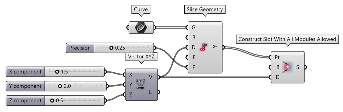
11.12.4. Definition: Slots from Slice Geometry: Curves
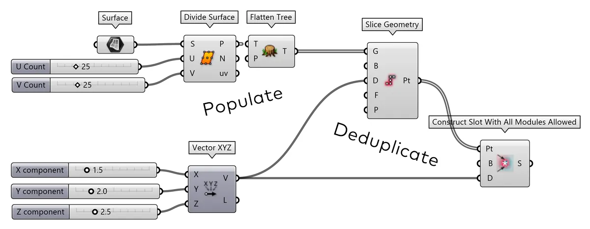
11.12.5. Definition: Slots from Slice Geometry: Surfaces
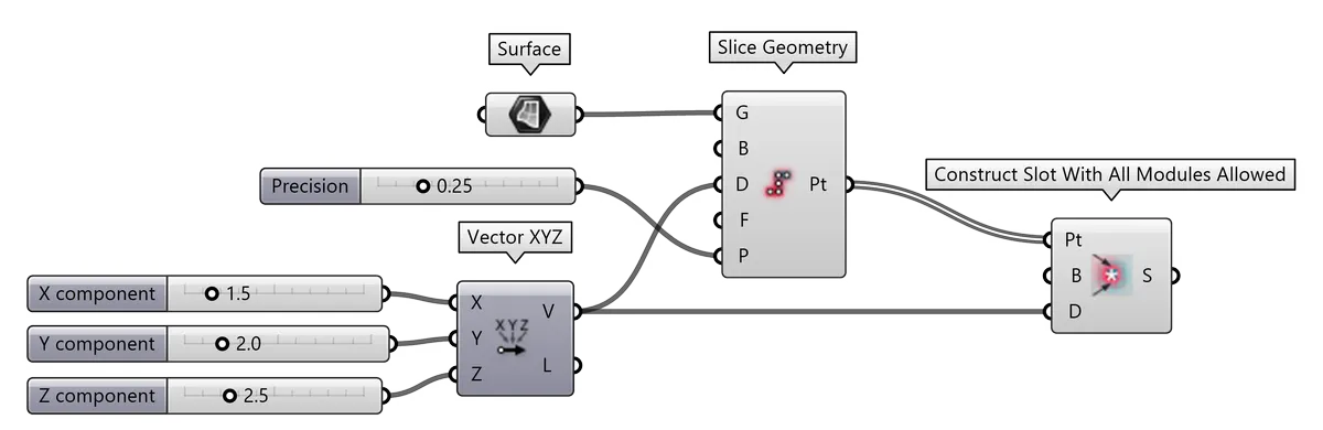
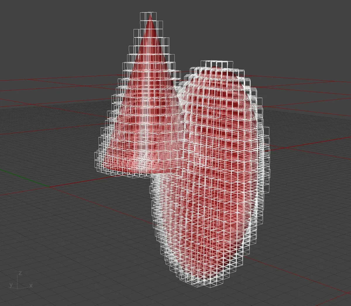
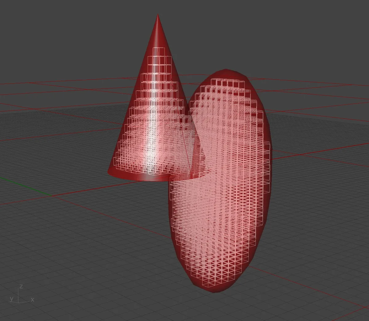
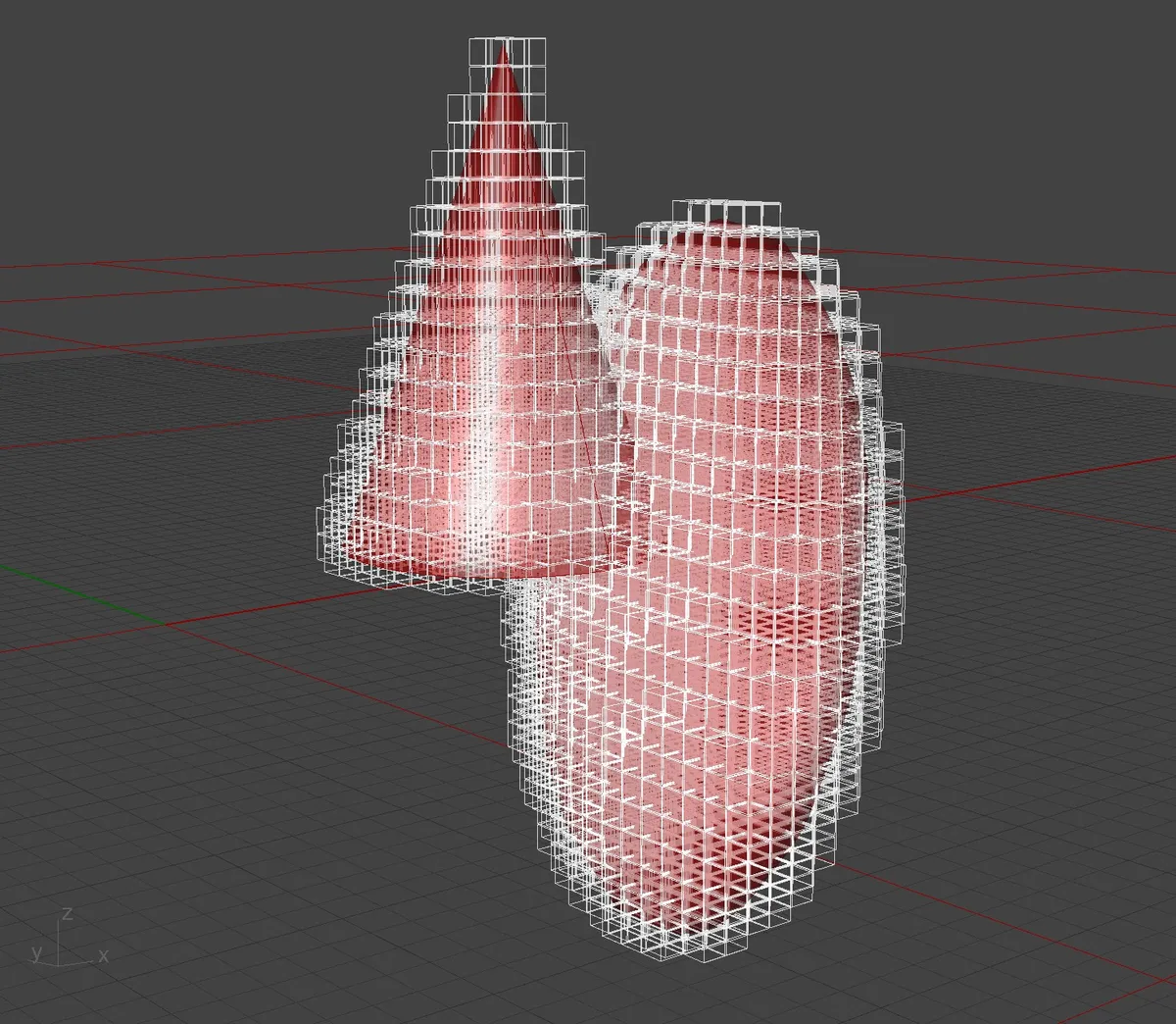
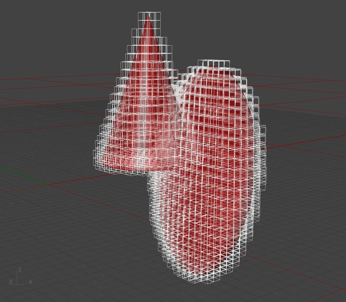
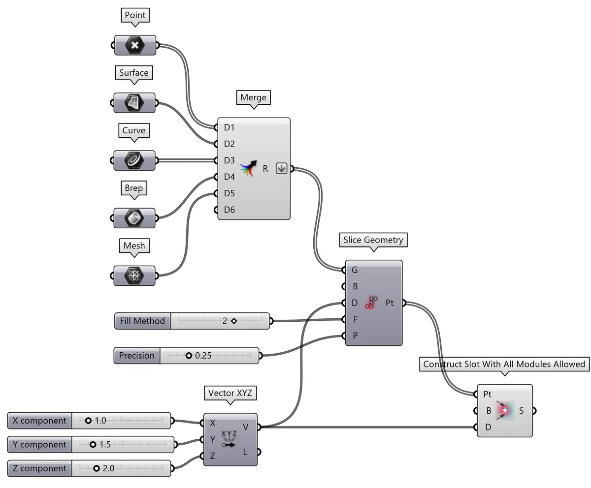
11.12.6. Definition: Slots from Slice Geometry: Mesh and Brep volumes
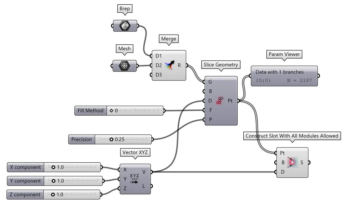
| Fill method 0: wrap geometry surface. Output Slots count = 2187. | Fill method 1: fill geometry volume. Output Slots count = 2010. | Fill method 2: wrap surface and fill volume. Output Slots count = 4165. | Fill method 3: wrap geometry surface (experimental). Output Slots count = 1784. |
|---|---|---|---|
 |
 |
 |
 |
11.12.7. Definition: Slots from Slice Geometry: Miscellaneous geometry
11.13. Allowing certain Modules in certain Slots
Slots are distinct discrete cuboid chunks of space, that allow placement of certain ]Module or their Parts into the respective portion of space.
In the initial state of the solution, the Slots can either allow placement of any Module or its Part or a specified list of Modules. The latter is especially useful if certain areas of the Envelope should or should not contain certain Modules. The list of allowed Modules needs to be specified manually for each Slot, but this can be effectively achieved with the existing Grasshopper tools.
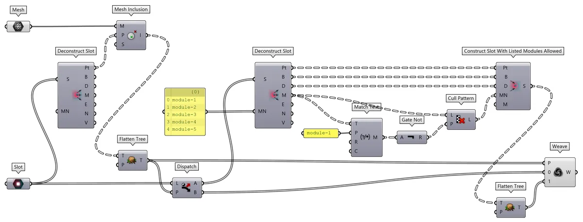
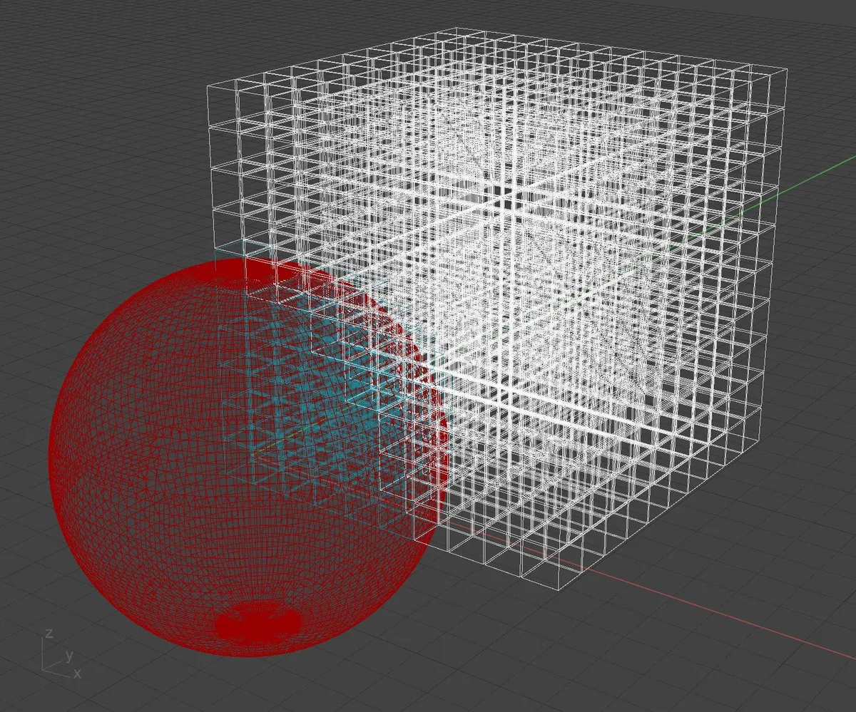
11.13.1. Definition: Allowing / Disallowing Modules in certain area
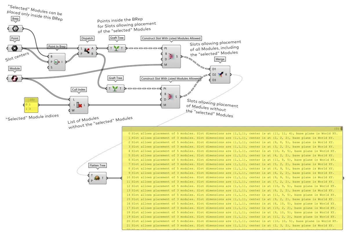
| Complete setup | Slots allowing placement of all Modules, including the "selected" Modules | Slots allowing placement of Modules without the "selected" Modules |
|---|---|---|
 |
 |
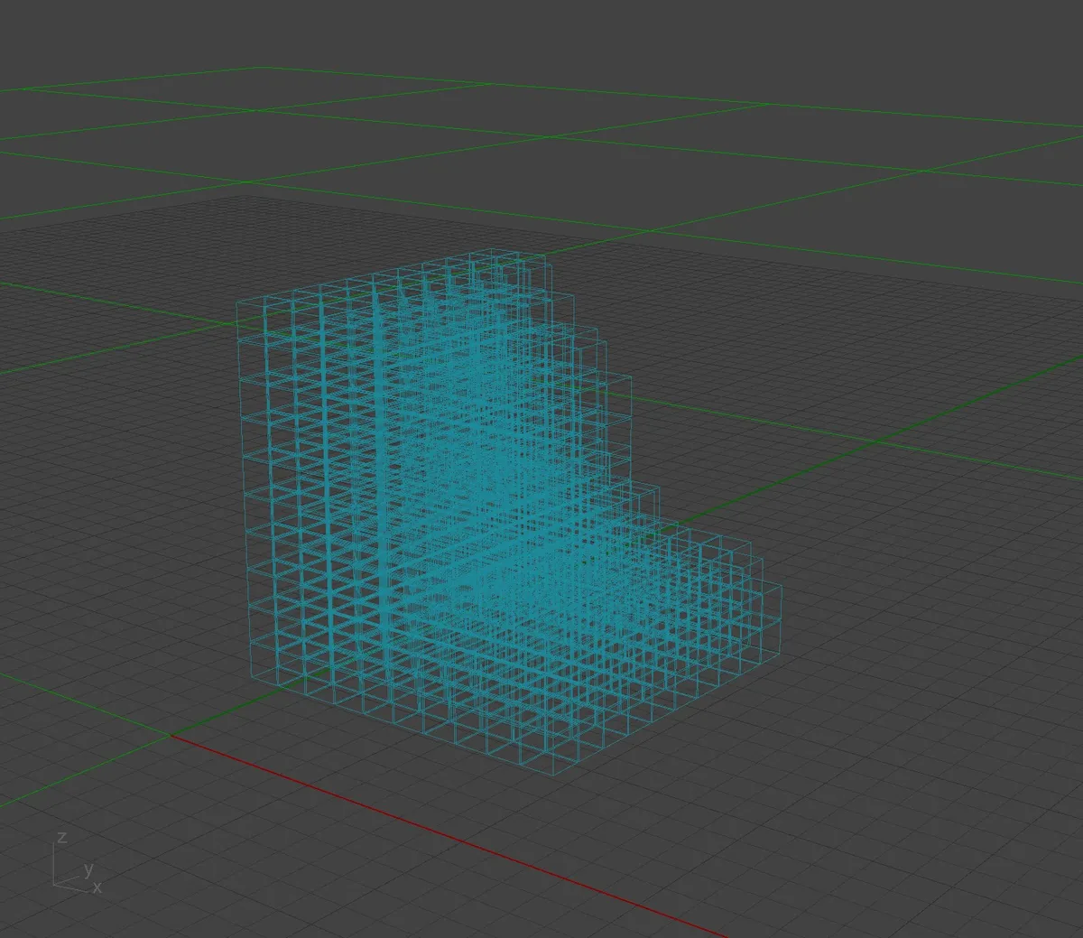 |
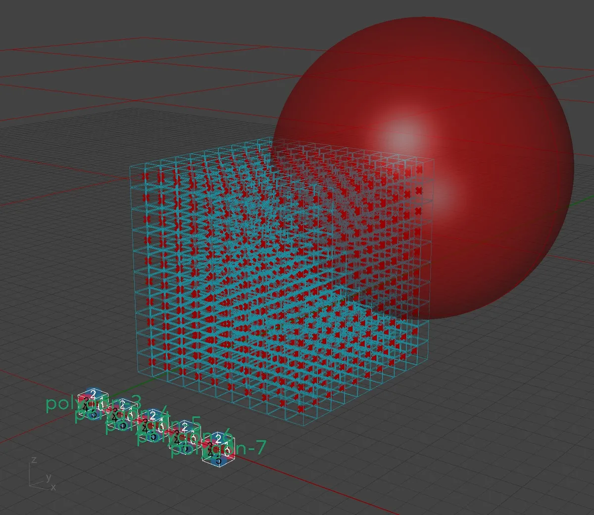
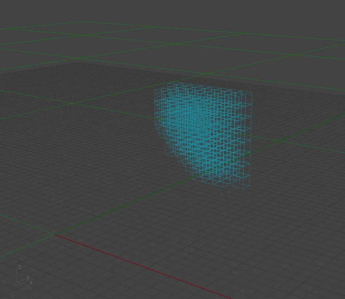
11.13.3. Definition: Allowing / Disallowing Modules based on attractor
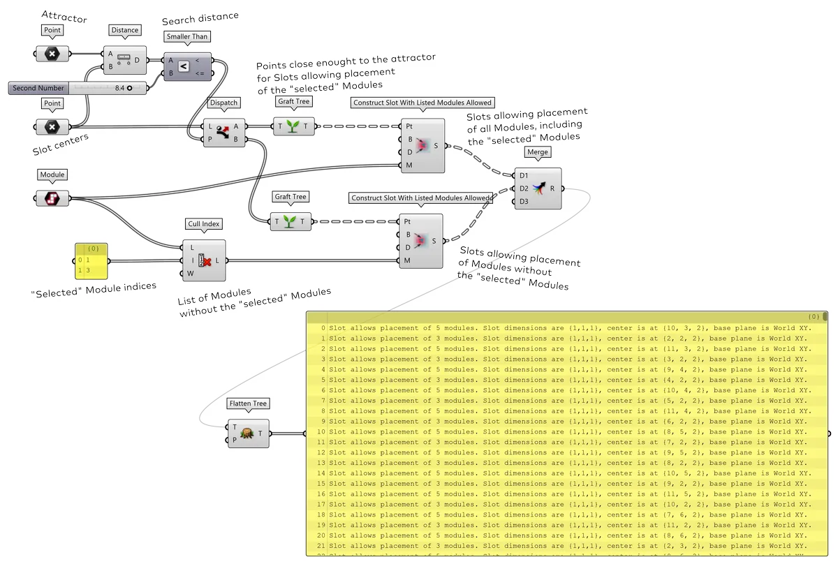
| Complete setup | Slots allowing placement of all Modules, including the "selected" Modules | Slots allowing placement of Modules without the "selected" Modules |
|---|---|---|
 |
 |
 |
11.13.4. Roulette approach to weighted probability
The Slots do not allow weighted probability of placing certain Modules but the weight can be simulated and distributed discretely. That means, allowing placement of a certain Module will be allowed in Slots more or less often in Slots of certain area. For each individual Slots there will have to be a decision to be made, whether it should or should not allow placement of a Module based on the probability factor.
Technically, this can be achieved by a roulette method: a random item will be chosen from a list of possibilities but the items will be multiplied in the list based on their probability.
11.13.5. Definition: Roulette - Choosing a binary weighted option
For example, the algorithm should choose from two options a and b, with
probability 3:2 in favour of option a, the list of options will contain
items a, a, a, b, b, out of which one random option will be chosen.
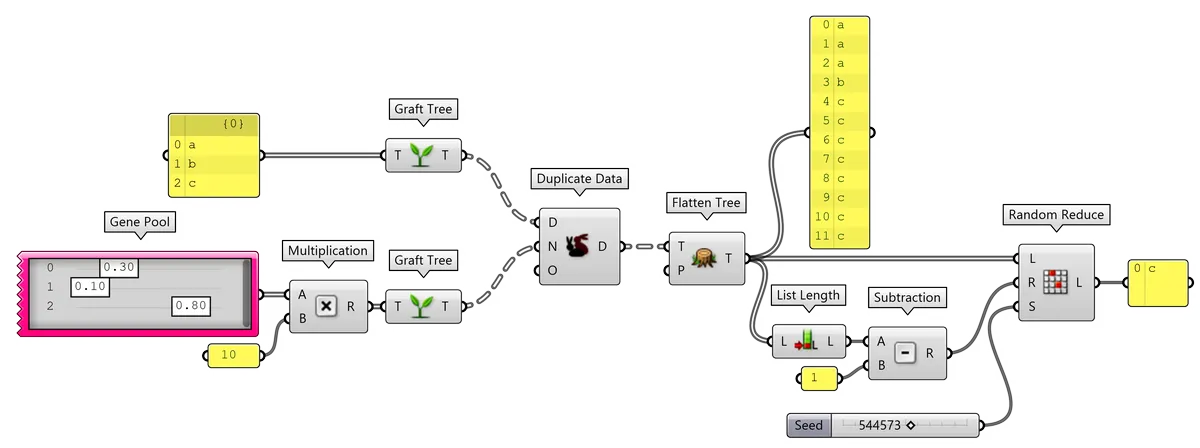
11.13.6. Definition: Roulette - Choosing one weighted option from multiple choices
For more items, the probability can defined as a number from range 0.0 to 1.0
with probabilities a=0.3, b=0.1, c=0.8, then the list of items will
contain a, a, a, b, c, c, c, c, c, c, c, c, out of which one random item will
be chosen.
11.13.7. Definition: Roulette - Choosing more weighted options from multiple choices
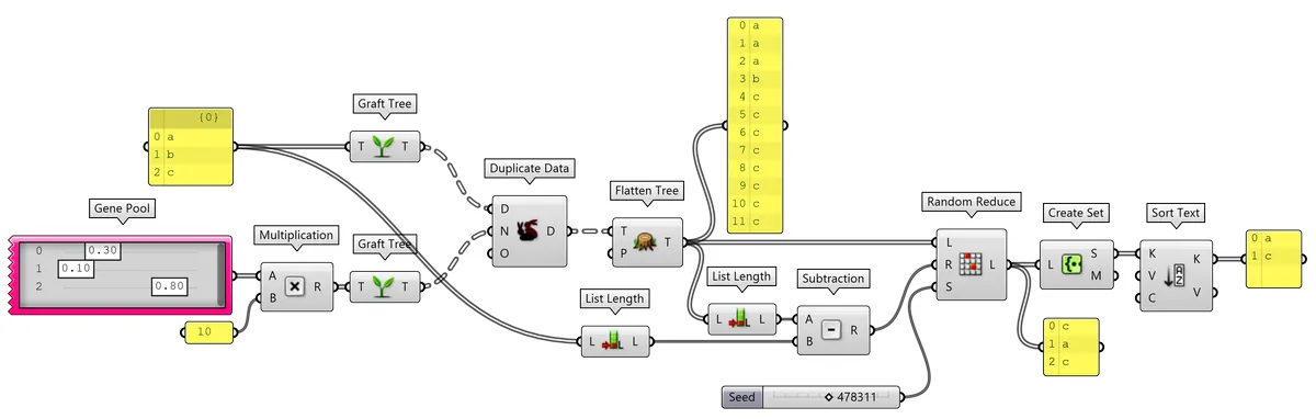
It the random weighted selection expects results with more items, it is possible
to use the same strategy. The
previous example
could describe a Slot, that can contain 3 Modules, witch probabilities
a=0.3, b=0.1, c=0.8. The list of items will be extended to
a, a, a, b, c, c, c, c, c, c, c, c and randomly reduced back to 3 options.
Such result will most probably contain c, c, c, which then will be
deduplicated to c or a, c, c deduplicated to a, c. This way it is
possible
to keep only the most probable modules in a Slot.
11.13.8. Definition: Allowing Modules based on vertical gradient
Employing the roulette approach, it is possible to use gradient values calculated from vertical position to a probability of Module placement.
| Slots allowing placement of "module-1" | Slots allowing placement of "module-2" | Slots allowing placement of "module-3" | Slots allowing placement of "module-4" |
|---|---|---|---|
 |
 |
 |
 |
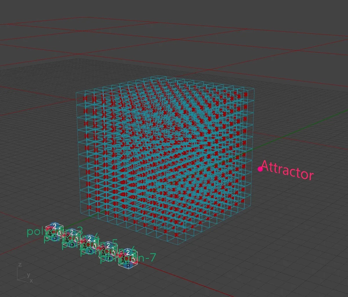
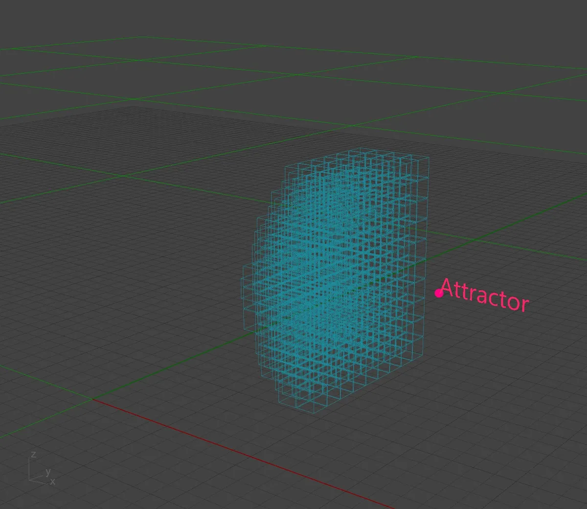
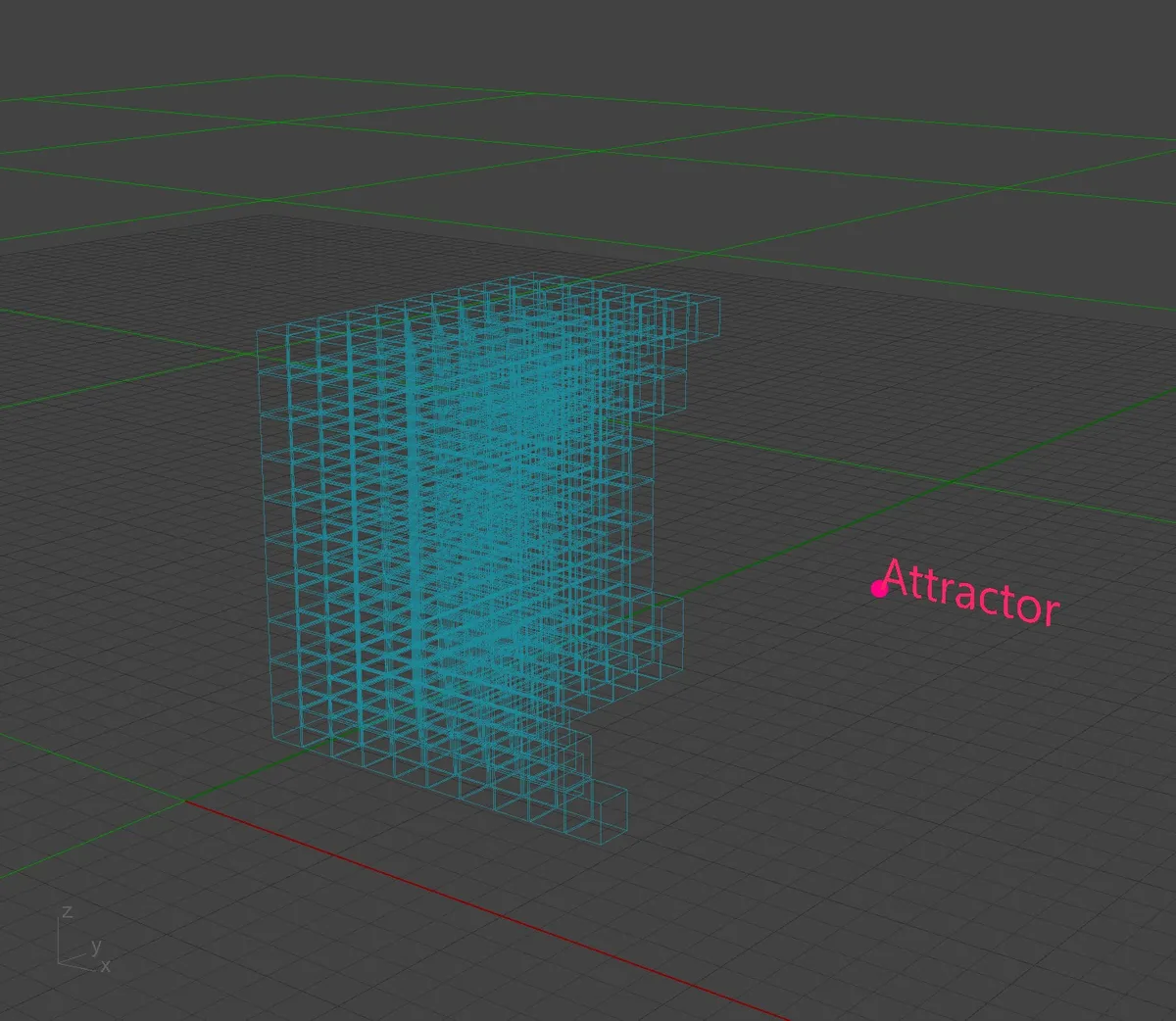
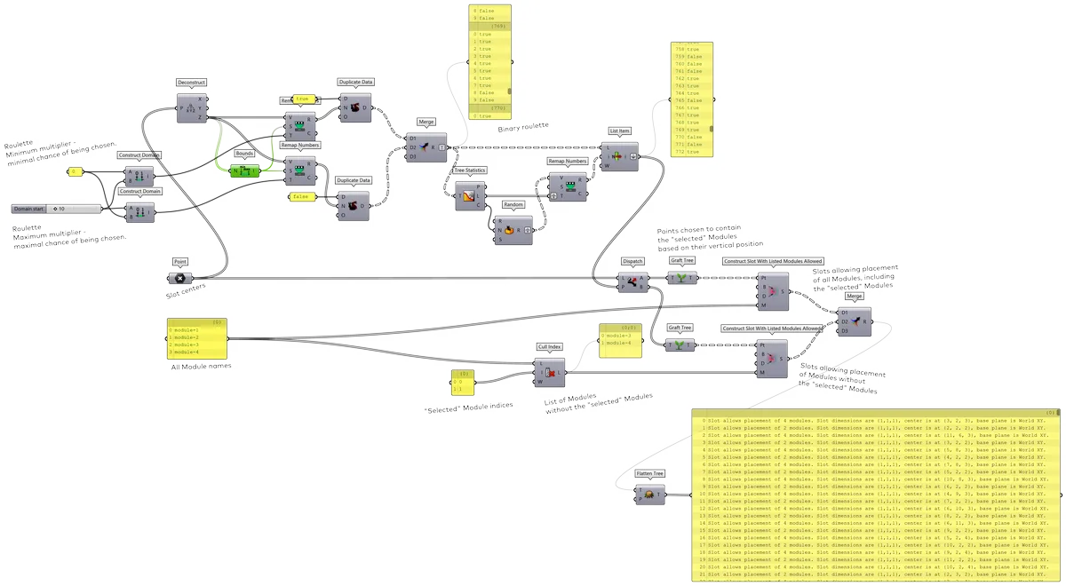
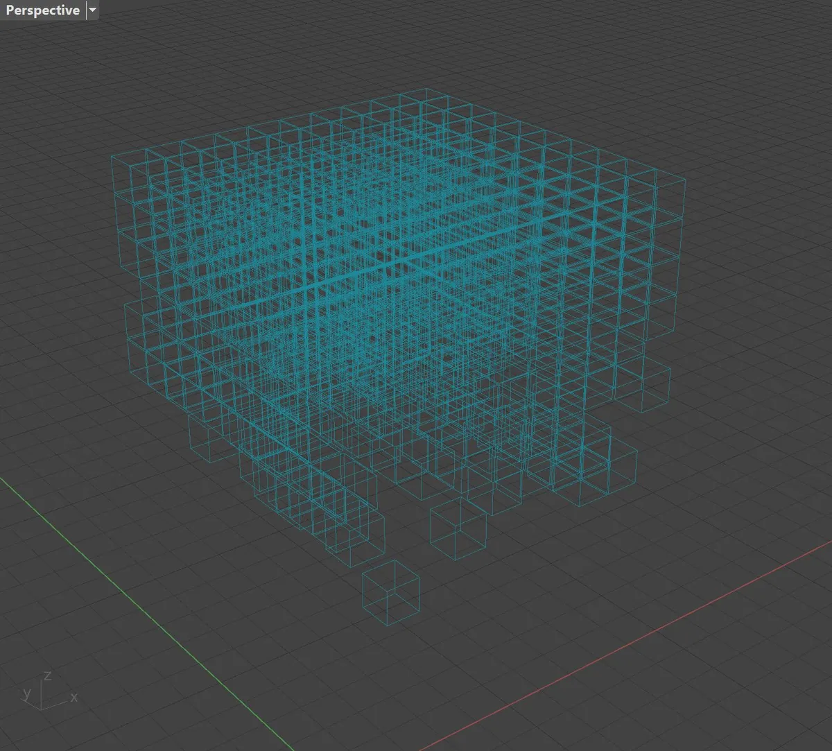
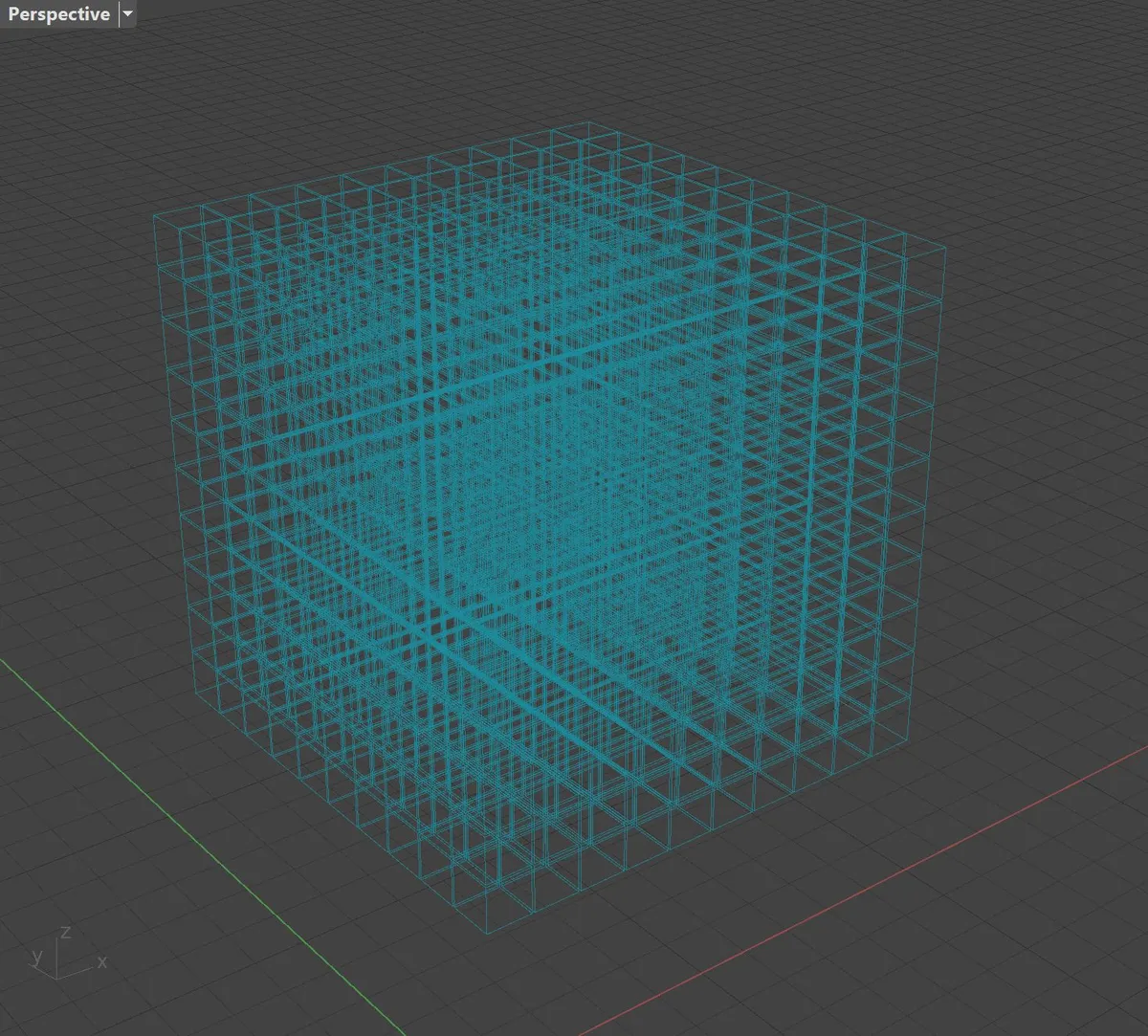
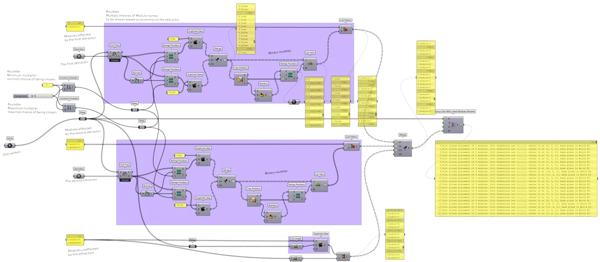
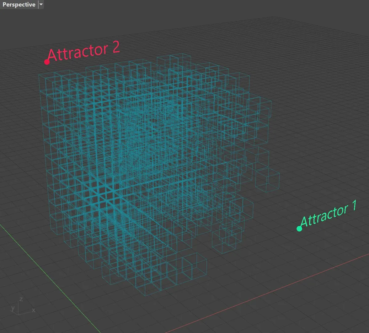
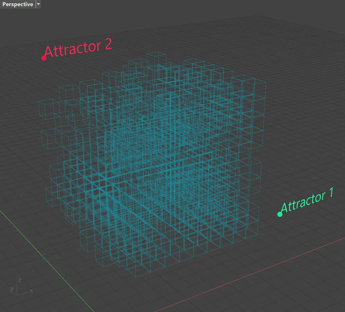
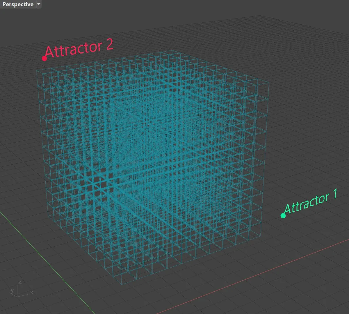
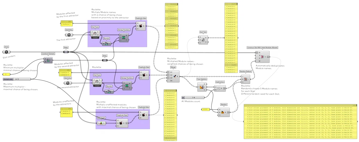
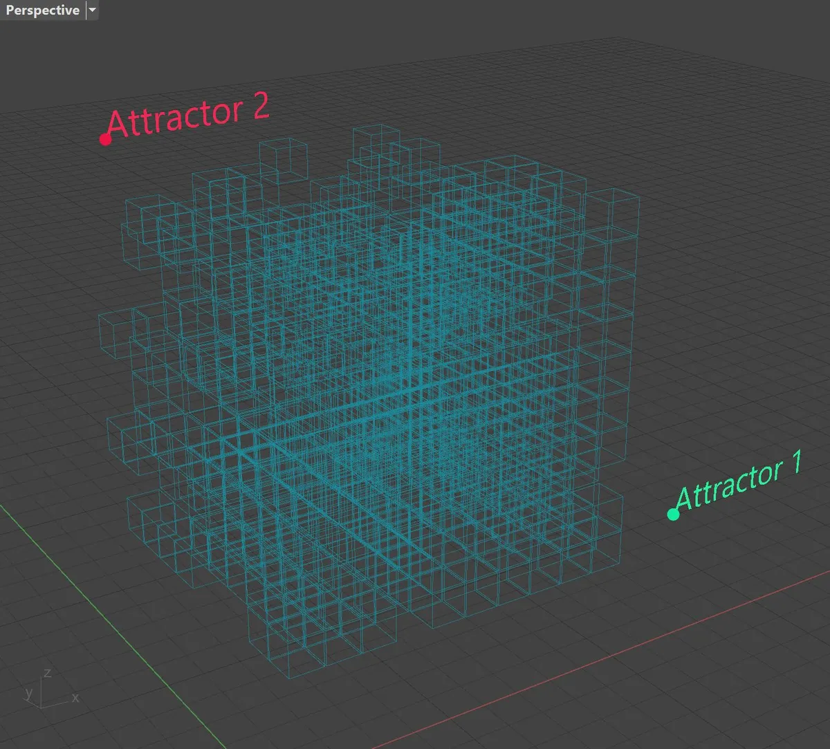
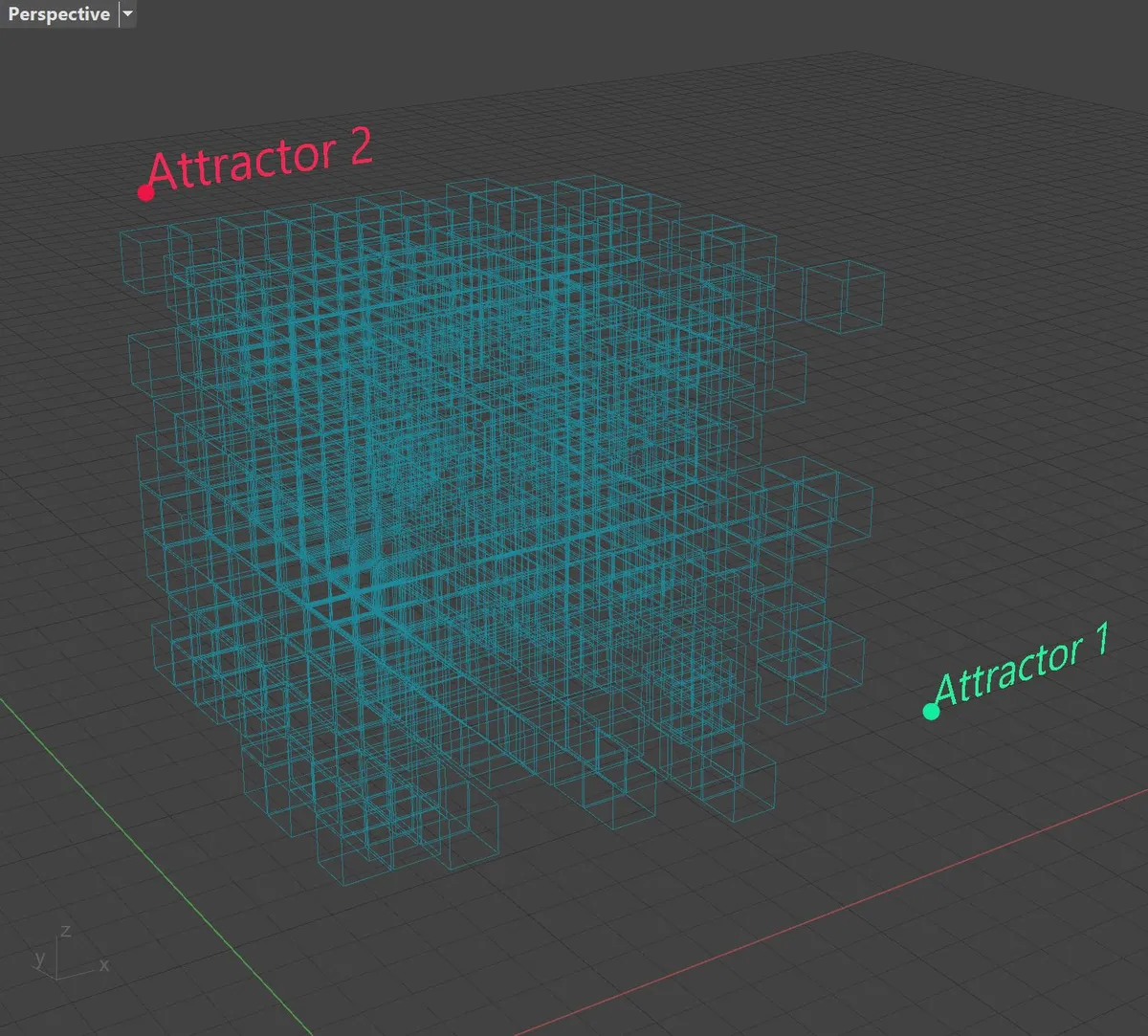
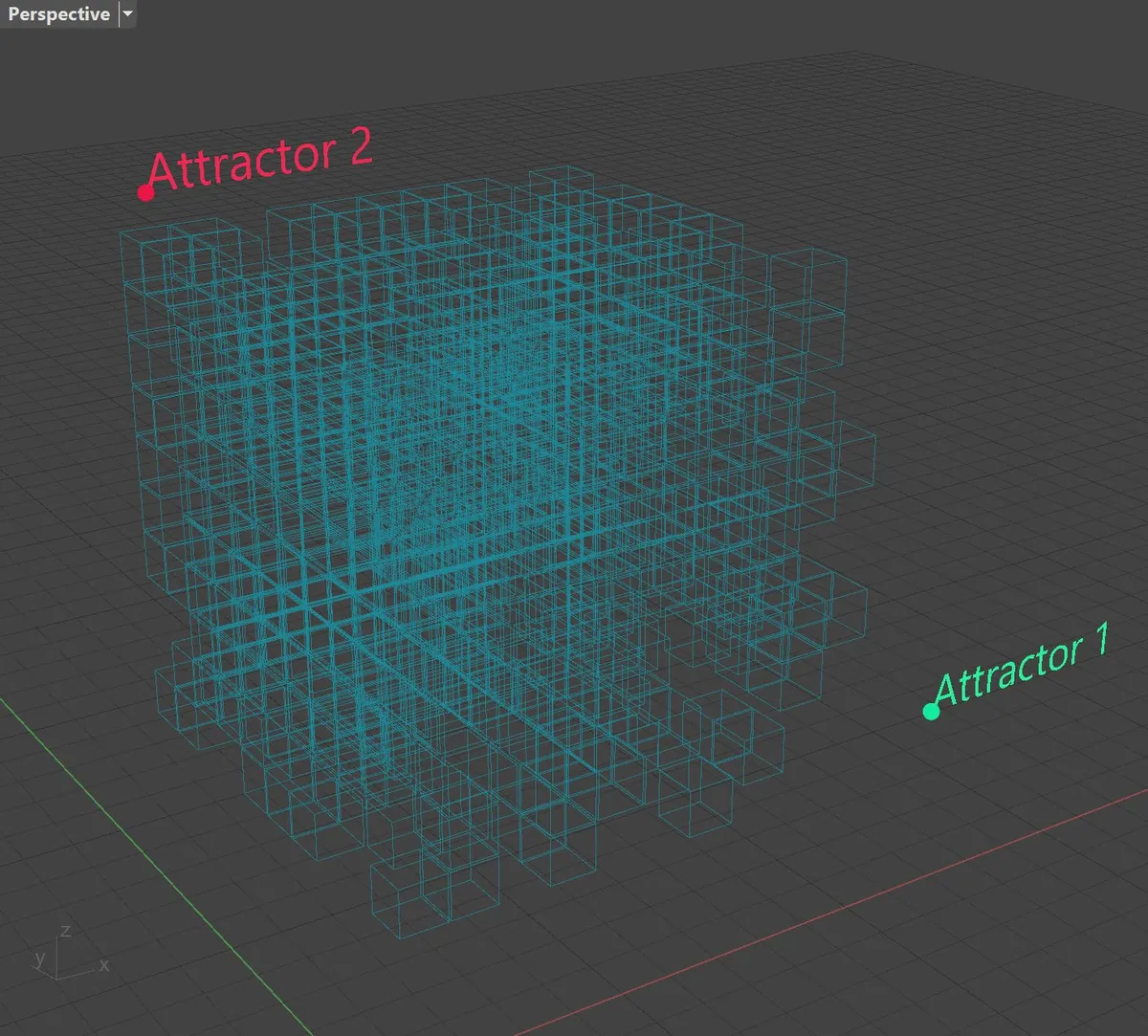
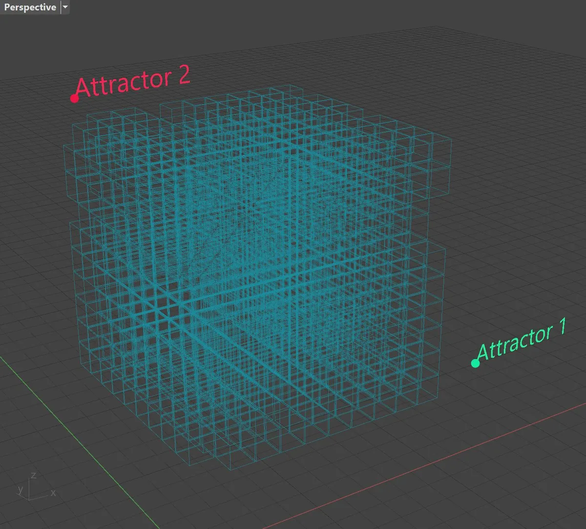
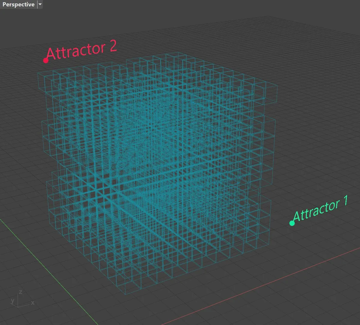
11.13.9. Definition: Allowing Modules based on multiple attractor gradients
Employing the roulette approach, it is possible to use gradient values calculated from distance of an attractor to a probability of Module placement.
Example based on binary roulette
 Download
| Slots allowing placement of "module-1" | Slots allowing placement of "module-2" | Slots allowing placement of "module-3" | Slots allowing placement of "module-4" | Slots allowing placement of "module-5" |
|---|---|---|---|---|
 |
 |
 |
 |
 |
Example based on multiple weighted options roulette
 Download
| Slots allowing placement of "module-1" | Slots allowing placement of "module-2" | Slots allowing placement of "module-3" | Slots allowing placement of "module-4" | Slots allowing placement of "module-5" |
|---|---|---|---|---|
 |
 |
 |
 |
 |
11.14. Fixing Modules in Envelope before running the Solver
In certain cases it is desired to place certain Modules into certain Slots even before running the Monoceros WFC Solver. The solution will then respect the position of such placed Modules and the rest of the solution will follow according to the given Rule set.
In Monoceros it is possible to achieve this by constructing the respective Slots with the list of Allowed Modules containing only the desired Module. If the Module consists of more Parts it is sufficient to construct a single Slot with the list of allowed Modules containing exclusively the desired Module. Monoceros will place one of the Module Parts into the Slot and the rest into the adjacent Slots as long as they are allowed to be place there, too.
Note: Due to the way Monoceros exposes the vanilla Wave Function Collapse algorithm, it is not possible to place a specific Module Part into an exact position. The Monoceros WFC Solver picks any Module Part to be placed into a Slot allowing placement of the Module.
Note: Placing Modules manually may cause longer search for a valid solution or completely eliminate an existence of a valid solution.
11.15. Disallowing certain Modules from certain Slots
Similarly to allowing certain Modules to be placed into certain Slots, it is possible to disallow placement of certain Modules into certain Slots.
Because Monoceros does not recognize disallowing, it is necessary to remove the disallowed Module name from the list of allowed modules for the respective Slots. For newly created Slots the list of allowed Modules should contain only the allowed Module names - the disallowed Module's name should be removed from the list manually prior to constructing the Slot.
Existing Slots can be deconstructed and reconstructed with a reduced list of allowed Modules. The original Slots should be replaced with the reconstructed ones.
11.15.2. Definition: Disallowing Modules in existing Slots
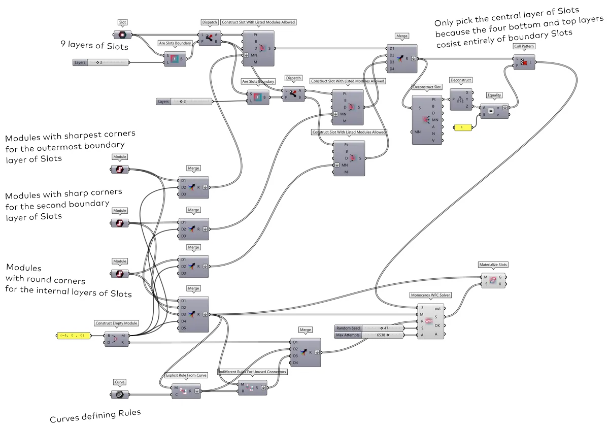
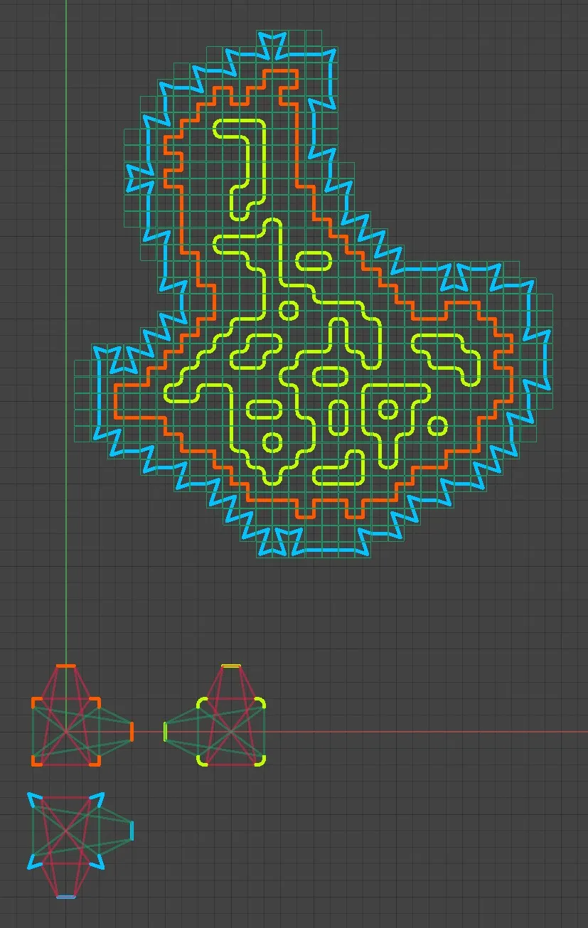
11.16. Enforcing specific modules at the boundary of the Envelope
If specific Modules are allowed to be placed at the boundary of the Envelope but their placement should be enforced, it is possible to identify Slots at the boundary of the Envelope using the Are Slots Boundary component, deconstructing the boundary Slots and allowing or disallowing the desired Modules from these Slots.
11.16.1. Definition
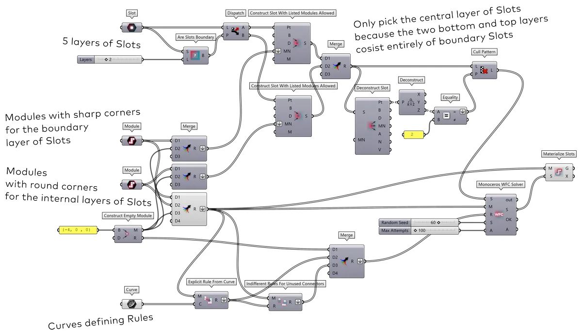
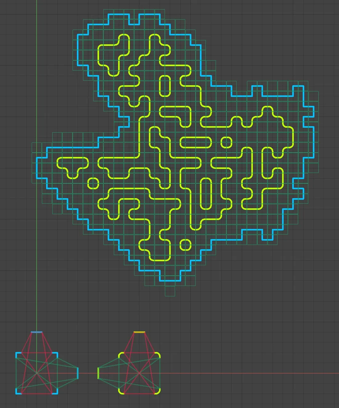
Note: The example shows a 2D setup. Monoceros is inherently 3D and so is the Are Slots Boundary component, therefore the setup is first constructed in 3D (5 horizontal layers of Slots) but only the middle horizontal layer of Slots enters the Solver. The two bottom and top layers consist entirely of boundary Slots.
11.16.2. Definition: Identifying more boundary layers
If more than one boundary layer of Slots should be isolated, the Are Slots Boundary component can be used multiple times, each time on Slots identified as inner (non-boundary).
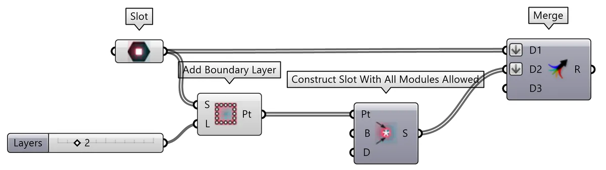
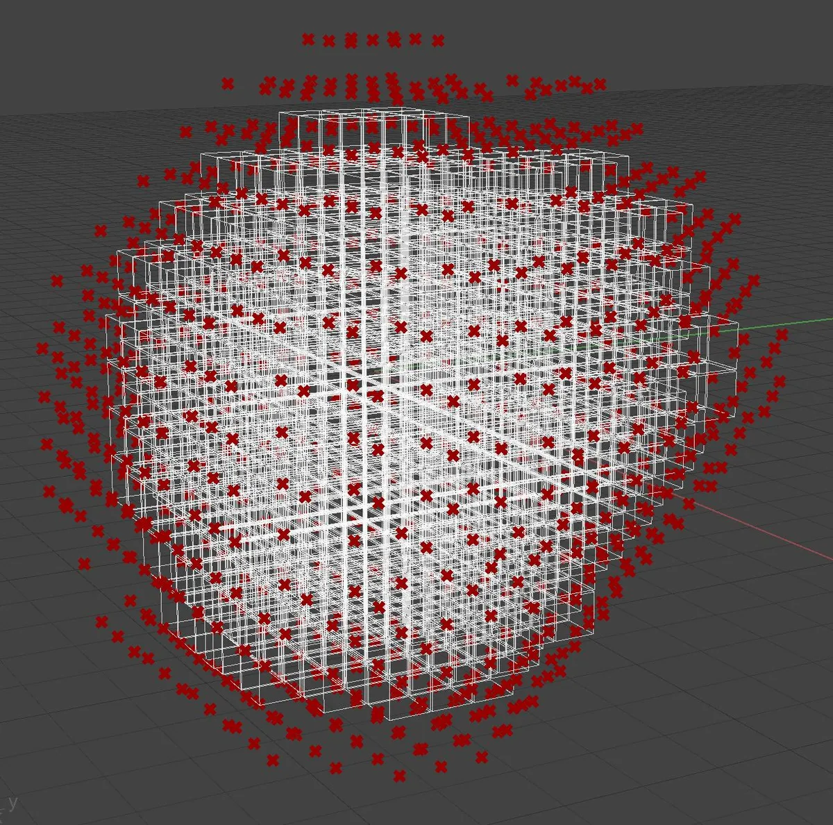
11.17. Growing the boundary of the Envelope
It is possible to wrap the existing Envelope of Slots into another layer of Slots. The Add Boundary Layer component generates a collection of Slot center points that can be converted into Slots, which will form a single added layer to the existing Envelope.
11.17.1. Definition
11.18. Materializing results
A correct result of the Monoceros WFC Solver is a collection of deterministic Slots, which allow exactly one Module Part to be placed. This is still not the final stage of the discrete assembly process because the solution is not yet Materialized, which is a process of placing Module Geometry into its respective Slots.
The output of Materialize Slots component is a data
tree with paths { module index, slot index }, where module index is the
order of the placed Module in the input list of Modules and slot index is the
order of the target Slot in the input list of Slots. Each branch then contains
all geometry items of the respective Module.
Note: Due to the way Monoceros treats Module Parts, only the first Part of each Module is placed into its Slot, leaving the remaining Slots containing the Module empty (their index will not even appear in the Materialize Slots component output data tree).
The geometry output of the Materialize Slots component is intended for further use in Grasshopper. Therefore, if the intention is to bake the output of the WFC already in this stage, it is recommended to bake the Materialize Slots component. The result of such bake is a collection of block instances, which are significantly smaller than full-fledged geometry and all blocks of one type can be edited at once.
Note: The viewport rendering of materialized geometry may be slow on some computers. This makes the Materialize Slots component one of the slowest part of a Grasshopper Monoceros definition. To speed it up, it is recommended to disable preview of the Materialize Slots component prior to connecting wires to its inputs.
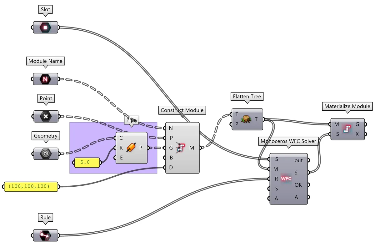
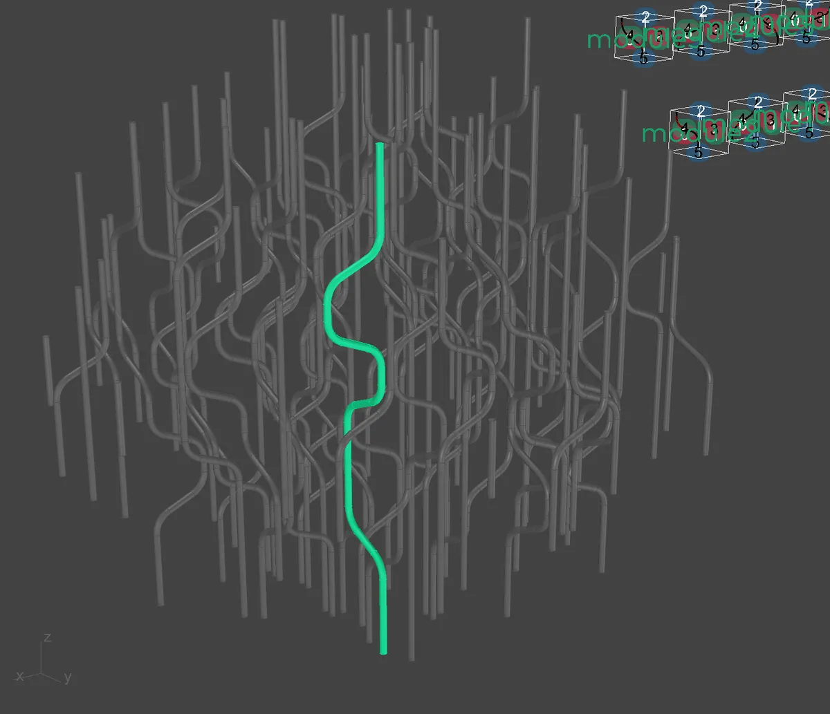
11.19. Proto-results and custom materialization
In some cases the final geometry of a Grasshopper definition does not have to be the one stored in the Monoceros Modules. The Modules can contain some proto-geometry instead and the final geometry is then constructed in Grasshopper after materialization.
A typical case may be structures that are not meant to be discrete, but rather continuous. The Modules should then contain only the skeleton of such structure, which will be joined and wrapped into volumes after the materialization of the WFC assembly.
11.19.1. Definition
The usual approach would be to embed the final version of the geometry into the Modules themselves. The materialized geometry is organized in data tree representing the Slot and Module order, rather than any semantic logic. Each element of the result is a separate geometry.
 Download
example based on the
Mondieu example and its
Rhino file.
Download
example based on the
Mondieu example and its
Rhino file.
Modules with embedded final version of the geometry
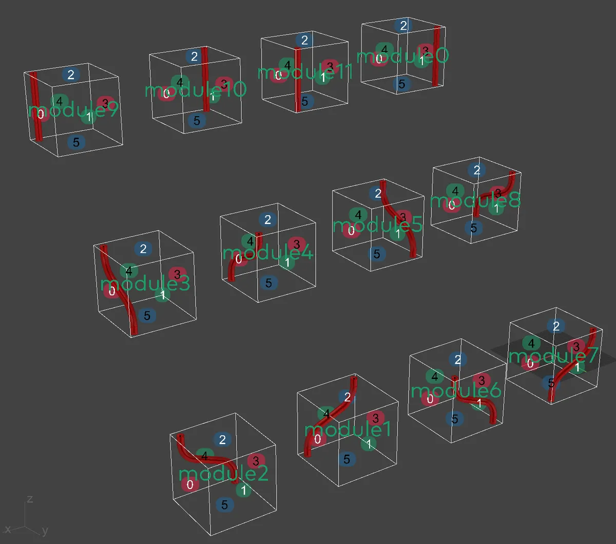
Single element of the result
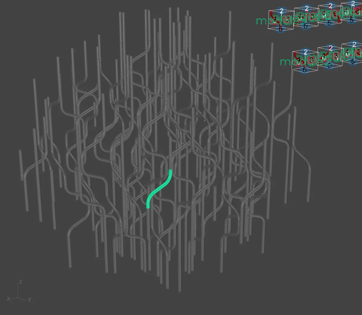
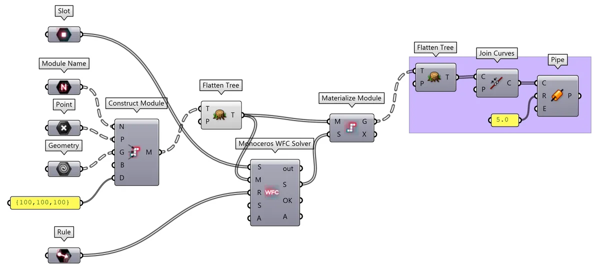
Instead it is possible to use a proto-geometry and process it after Materialization. In this case, the pipes are represented by their skeleton curves, which can be eventually joined into continuous curves and only then turned into valid continuous pipes.
 Download
example based on the
Mondieu example and its
Rhino file.
Download
example based on the
Mondieu example and its
Rhino file.
Modules with proto-version of the geometry
Single element of the result
11.20. Using the transform data to materialize the result
In very special cases, the geometry does not have to enter the
Modules at all. Instead, the
Monoceros WFC Solver runs on the Rule set
an Modules with no geometry and so does the
Materialize Slots component. Its Transform output
contains transformation data, that can be used to place any geometry from the
original Module location into all the Slots which should contain the
respective geometry.
This is especially useful if there are various geometry sets that could be used as the Module Geometry. These sets can be interchanged without the need of recalculating the entire Monoceros WFC solution.
Note: The geometry that should be placed using the Transform output needs to
be located and aligned properly: it should share the same location and Base
Plane orientation with the original Module.
11.20.1. Definition
11.21. Random seed and attempts count
During the Wave Function Collapse calculation, there are several moments when a random decision has to be made: if a Slot allows placement a equally valid Modules, the Monoceros WFC Solver chooses one random Module to be placed. Such situation can occur at several Slots at a time, therefore the Solver chooses a random Slot to process.
Like Grasshopper, also Monoceros uses seeded pseudo-random function. That means that the Monoceros WFC Solver generates the same solution for a constant Rule set and constant Modules and Slots every time and at every computer, as long as the seed is the same and vice versa, different seeds generate different outputs even on the same computer.
The WFC algorithm does not ensure there will always be a solution. Throughout the processing it can happen that the setup may not result in a valid output - some Slots may end up contradictory and allow placement of no Modules whatsoever. Such situation cannot be anticipated rr prevented, therefore it is necessary to make several attempts with different random decisions. The Monoceros WFC Solver component lets the user to define how many unsuccessful attempts should it make until it pronounces the setting unsolvable.
There is no good value for maximum attempts. For simple and well defined setups the Solver usually finds the solution in the first attempt but it is not rare that it takes more than a thousand attempts to find a solution in some cases. The mere fact that it requires more than one attempt shows, that the setup is problematic and may not be solvable at all.
There is no good value for the random seed. Changing the random seed for setups that produce solutions will result in various, yet equally good solutions. The properties and qualities of a solution are not related to the value of the random seed, therefore it makes no sense to compare one seed to another. For solutions that are hard to find it may happen, that for some random seeds the Solver requires less attempts than for others. This is only true until other inputs (Modules, Rules and Slots) remain unchanged.
11.22. Visualizing Rules
The Rules can be displayed in Rhinoceros viewport and baked using Rule Preview component. The Rule is shown as a line, connecting two Connectors that are allowed to be adjacent.
The color of the preview line indicates the orientation of the Connectors: red means X, green means Y and blue means Z. If the Rule allowing adjacency is Typed, the line carries also a label with the Type name.
Note: It is not always necessary to display all Rules or Rules for all Modules. The inputs can vary depending on the information that should be displayed.
11.22.1. Definition
11.23. Visualizing allowed Module couples
An Explicit Rule can be displayed also as an assembly of two Modules that are allowed to be adjacent.
Note: A Typed Rule can be converted into a collection of Explicit Rules prior to assembling.
The Module mentioned in the Rule first is considered a source, the second one a target. The source Module's Pivot is aligned to the assembly Base Plane, the target Module is aligned to source Module so that their adjacent Connectors are touching.
Note: The Assemble Rule component does not check the two modules for overlapping but the architecture of the WFC Solver prevents the overlaps in the actual solution.
If more Rules should be assembled at once, it is necessary to define an individual Base Plane for each assembly. The Base Planes need to be manually distributed so that the assemblies do not overlap.
11.23.1. Definition: Visualizing one Module couple
11.23.2. Definition: Visualizing a catalog of Module couples
12. FAQ
12.1. What is a good exercise to start using Monoceros?
The Wave Function Collapse is a very powerful tool but requires a lot of patience to learn. It is recommended to read the Subdigital WFC Book and understand the principles of WFC and its implementation in Monoceros before trying the first experiments in Grasshopper. It is especially important to understand that WFC is not a growth algorithm and how does it differ from other seemingly similar discrete assembly tools.
When learning Monoceros and building intuitive sensitivity, the following steps are recommended:
- Start as simple as possible
- Do not jump to complex setups too early
- Use a relatively small sphere to generate the Envelope
- Try defining a single simple Module - a vertical line
- Generate Indifferent Rules for all its Connectors
- Use the Monoceros WFC Solver and Materialize Slots components to finish the simplest assembly
- Define the first Explicit Rule allowing the Module to meaningfully connect to itself - bottom to the top or vice versa
- Try to figure out why there is no solution
- Allow the Module to be placed at the Envelope boundary
- Add Empty Module
- Add second Module - a horizontal line
- Figure out why does it not appear in the solution
- Try removing the Empty Module
- Add the third Module - an L shape that could connect the vertical and horizontal Module
- Construct Explicit Rule that connects the L Module with the other two Modules
- Try preventing the vertical and horizontal Modules to appear at the boundary and place the L Module there instead
- Add the Empty Module again
- Add an three other L shape Modules so that the Solver can generate closed rectangles
- Try to figure out why there are open shapes and prevent them
- Try creating a Rule set that generates closed zig-zag shapes
- Try replacing all Explicit Rules with Typed Rules
- Whenever hesitating, look for an answer in the Examples.
12.2. What does the error "World state is contradictory" mean?
It means there is no potential solution for the current setup. It can have several reasons:
- the Module Parts form a shape that cannot be assembled without an Empty Module
- the Envelope or its part is too small to place any allowed Module
- no Module is allowed to be placed at the boundary because the required Connectors are described by custom Rules and the Indifferent Rules were not automatically generated for them
- the Rule set does not allow for any viable assembly
12.3. Why the Solver cannot find any solution even after 1000 attempts?
Most probably because the Rule set is too specific and the solution is rare. Try making the Envelope significantly smaller without causing a a contradictory world state and increase the number of attempts.
Try changing the random seed, even though it only forces the Monoceros WFC Solver to try different random set of attempts.
If there is no solution even after 5000 attempts and several different random seeds, it is recommended to start over and build up the setup Module by Module.
It is also possible that the setup has no solution at all.
12.4. What makes a good Module?
The safest Module has only one Part but such Modules also generate unsurprising and simple outputs. A Module can consist of maximum 256 Parts, but it is recommended to keep the number of Module Parts under 10.
The Module has to be consistent and all its Connectors need to be described by at least one Rule, even if it should be an Indifferent Rule.
To achieve interesting results, the Module's content (in most cases its Geometry) should be semantically heterogenous or in other words, the boundaries of semantical parts should not match the boundaries of Modules. Said simply, the whole should be cut through the middle of a distinct part, rather than along its boundary. If the Modules should represent urban elements, they should not contain individual houses but rather a part of a house, part of a garden, part of a pavement and a bit of a road. If the WFC should compose a world map, good Modules are those that contain a coast line, not those that contain only the sea or the land.
12.5. What makes a good Envelope?
A good Envelope is aware of the size and shape of the Modules that should be placed into it.
If the Modules do not allow it, the Envelope should not have small parts sticking out, forming thin shells otherwise already the inital state of the Envelope may be contradictory.
12.6. Why does the Slice Geometry component give invalid results?
If the sliced geometry or its part reaches the boundary, edge or vertex of a potential Slot or a Module Part, it means that the part may belong into two (if on surface), four (if on edge) or even eight (if on vertex) neighboring grid cells. It is difficult for the component to decide into which one it should be placed. Any approach would be only approximating and could give wrong results in edge cases.
Therefore the Slice Geometry component completely resigns on any decision making in unambiguous situations. Therefore it is strongly recommended to generate Slot Points and Module Part Points manually whenever possible.
12.7. How to set a Rule for a Module distant two or more Slots?
It is not possible. The Monoceros Wave Function Collapse implementation allows to specify only immediate adjacency.
For specific cases of 1D and 2D aggregates it is possible to use the remaining dimension to specify Modules with no Geometry spanning over more Parts / Slots with Rules at Connectors farther apart.
12.8. Are block instances or groups supported by Monoceros?
No. These data types are not part of the usual geometrical hierarchy in Grasshopper.
Construct Module and Slice Geometry components support the following geometry types and their derivatives:
- Point
- Curve (and Line, Arc, Circle etc.)
- Surface (and Sphere etc.)
- Brep / Polysurface (and Box etc.)
- Mesh
The architecture of Monoceros expects a small number of lightweight Modules. In such case it should not be a performance problem to embed the geometry into the Modules. The geometry itself is not being used for any calculations until the Modules reach the Materialize Slots component.
Two things are happening in the Materialize Slots component:
- it outputs the Module Geometry in a data tree. Each branch path represents
{ module index, slot index}, wheremodule indexis the order in which the Modules were passed into the Materialize Slots component andslot indexis the order in which the Slots were passed into the Materialize Slots component. Each branch contains a complete list of geometry brought by the respective Module into its Slot. Note: Only the Slots containing the first Part of each Module contain the Module Geometry to prevent duplicate geometry entries for multi-part Modules. Displaying all materialized geometry in Rhinoceros viewport may be slow, therefore it is recommenced to disable preview for the Materialize Slots component. The output geometry may be used for further Grasshopper processing or evaluation. - it bakes the module geometry as block instances. This means the geometry
exists in Rhinoceros only once and all its instances are just references to
the original block. This way it is possible to modify all instances of
geometry of each Module type at once by modifying any of the blocks. In most
cases it also means a significantly smaller Rhinoceros
.3dmfile.
13. Partners
Developed at Subdigital.
Supported using public funding by Slovak Arts Council.

14. MIT License
Copyright (c) 2021 Subdigital | Ján Pernecký, Ján Tóth
Permission is hereby granted, free of charge, to any person obtaining a copy of this software and associated documentation files (the "Software"), to deal in the Software without restriction, including without limitation the rights to use, copy, modify, merge, publish, distribute, sublicense, and/or sell copies of the Software, and to permit persons to whom the Software is furnished to do so, subject to the following conditions:
The above copyright notice and this permission notice shall be included in all copies or substantial portions of the Software.
THE SOFTWARE IS PROVIDED "AS IS", WITHOUT WARRANTY OF ANY KIND, EXPRESS OR IMPLIED, INCLUDING BUT NOT LIMITED TO THE WARRANTIES OF MERCHANTABILITY, FITNESS FOR A PARTICULAR PURPOSE AND NONINFRINGEMENT. IN NO EVENT SHALL THE AUTHORS OR COPYRIGHT HOLDERS BE LIABLE FOR ANY CLAIM, DAMAGES OR OTHER LIABILITY, WHETHER IN AN ACTION OF CONTRACT, TORT OR OTHERWISE, ARISING FROM, OUT OF OR IN CONNECTION WITH THE SOFTWARE OR THE USE OR OTHER DEALINGS IN THE SOFTWARE.